How to stretch a 3D model between two coordinates with python

Hello, Am working on a simulation app, And I faced the issue which is:
I want to stretch a 3d model between two specific coordinates (I want for each model the beginning point and destination point has different Z coordinates this will allow me to stretch the model).

So I want to put this model like its beginning point(X1, Y1, Z=5) and destination point(X2, Y2, Z=10).

What I found is: we have a setPos(x,y,z) But this function Will set the model according to its centre point

So how should I do that?

Ah–that looks like a matter of “shearing”, as applied by “setShear” (see the API here.)

I’ll confess that I haven’t used this feature overmuch myself, so I don’t have specific advice on what values to provide, but I’d suggest playing around with the “setShear” set of methods and trying to figure out what produces good values for your situation.

1 Like

Thank you, I will read about right now

1 Like

It looks like only horizontal shearing is available using those NodePath.set_shear methods. For example, if your fence model lies in the XZ-plane, you will want to apply a shear of (0., shear_factor, 0.), with shear_factor being the shxz parameter value. Applying this to the smiley model, you would get this:

Horizontal lines stay horizontal; only the vertical lines now have a slope. What you want is probably the opposite.

Although it doesn’t seem possible using the available methods, this can be done using a bit of matrix math. A shear matrix is limited to horizontal shearing as well, but by transposing it you end up with the vertical shear that you need:

shear_factor = .5
shear_mat = Mat4.shear_mat(0., shear_factor, 0.)
shear_mat.transpose_in_place()
model = base.loader.load_model(my_model_filename)
# the order in which matrices are multiplied is important;
# the shearing should be applied before other transform types,
# so the shear matrix needs to come first in the multiplication
# with the original model matrix
model.set_mat(shear_mat * model.get_mat())

If you apply the above code to the smiley model, you would get something that is probably more like how you want it:

Note that the value that you use for the shear factor is the tangent (or cotangent) of the slope angle.

Hope this helps! :slight_smile:

4 Likes

Thank you so much for this helpful answer.
I think it will work for me. But the only issue remaining and I think it is about math, how we can get the slope angle in 3D So we can get the shear factor.

Alternatively, I suspect that you could either model the fence on its side–such that the horizontal lines were vertical and vice versa–and then rotate it.

But perhaps more easily, one can use nested NodePaths to apply a vertical shear:

Simply put, what one does is to place the target NodePath under a “holder” NodePath. This holder is then rotated through ninety degrees, and the target NodePath is rotated through ninety degrees in the opposite direction–the result thus being that there is no apparent rotation. One then applies the shearing-factor to the holder.

This causes the holder to be sheared along its horizontal plane–which is at ninety degrees to that of the target NodePath. As a result, the target NodePath ends up sheared along its vertical plane! :slight_smile:

You can see this in action here:

And a short snippet of demonstrating the idea here:

        holder = render.attachNewNode(PandaNode("mew"))
        # Rotate the holder through ninety degrees
        # Which axis should be rotated around depends on the
        # orientation of the object, I imagine.
        holder.setR(90)

        mew = loader.loadModel("untitled")
        mew.reparentTo(holder)
        # Rotate the model through ninety degrees in the manner
        # opposite to the holder's rotation
        mew.setR(-90)

        # And now, shear the holder!
        holder.setShear(0, 0.75, 0)
2 Likes

It should be possible to get the shear factor directly without knowing the angle, by dividing the horizontal difference in position (i.e. X2 - X1) by the vertical difference (Z2 - Z1). It might also be the other way around and I’m not sure of the sign (subtraction order) either; you’ll have to try around a bit.

1 Like

I can only add that to implement your idea, you need to use procedural model generation. Which guarantees the correct geometry and texture mapping. It’s more complicated than it seems, you can’t just distort the model in the right direction.

1 Like

And how can I implement that, Actually I am a newbie with panda3d, is there any tutorial that can help me?
And which way do you think it’s complicated, you mean procedural model generation Or the way that guys said?

I may be mistaken, but I think that you can likely get at the least pretty close to the desired effect with shearing.

As to procedural generation, that is a rather more powerful tool–and perhaps a less fiddly one than shearing.

The manual discusses it here:
https://docs.panda3d.org/1.10/python/programming/internal-structures/procedural-generation/index

I’m not sure offhand of whether there are any tutorials on the subject, but perhaps a search of the forum will turn one up.

2 Likes

I think on the contrary, you need to take care of many things, for example, calculating the lighting normals and so on.

@Pythonic_Person

Check out this library. Based on it, you can learn about how procedural generation works.

2 Likes

Okay, that is a fair point.

Try shearing first. If that doesn’t give desirable results, you could indeed resort to procedural model generation. If you need help with that, you might want to check out my procedural geometry samples. Especially basic.py could be helpful.

2 Likes

Any ideas how to keep the original Z coordination without going the model down?

Well, the offset should be calculable (I think that it comes down to some trigonometry), so you could perform that calculation and then offset the object appropriately.

Judging from the screenshot in your first post, the origin of your fence model is at the bottom center, so the vertical offset needed to keep the sheared model from sinking into the ground should be equal to the shear factor multiplied by half the width of the fence model:

offset = abs(shear_factor) * fence_width * .5
fence_model.set_z(fence_model.get_z() + offset)
2 Likes

You don’t need the angle; all you need is the shear factor, which should be this (if fence_segment.get_length() gives the horizontal size of the fence segment):

                shear_factor = height / fence_segment.get_length()  # ex: height = 5, segment = 40

So the code might work better like this:

            if fence_segment[0][2] != fence_segment[1][2]: # has different Z
                height = fence_segment[1][2] - fence_segment[0][2]
                shear_factor = height / fence_segment.get_length()  # ex: height = 5, segment = 40
                shear_mat = Mat4.shear_mat(0., shear_factor, 0.)
                shear_mat.transpose_in_place()
                fence_segment_model.set_mat(shear_mat * fence_segment_model.get_mat())
                offset = abs(shear_factor) * fence_segment.get_length() * .3
                fence_segment_model.set_z(fence_segment_model.get_z() + offset)
1 Like

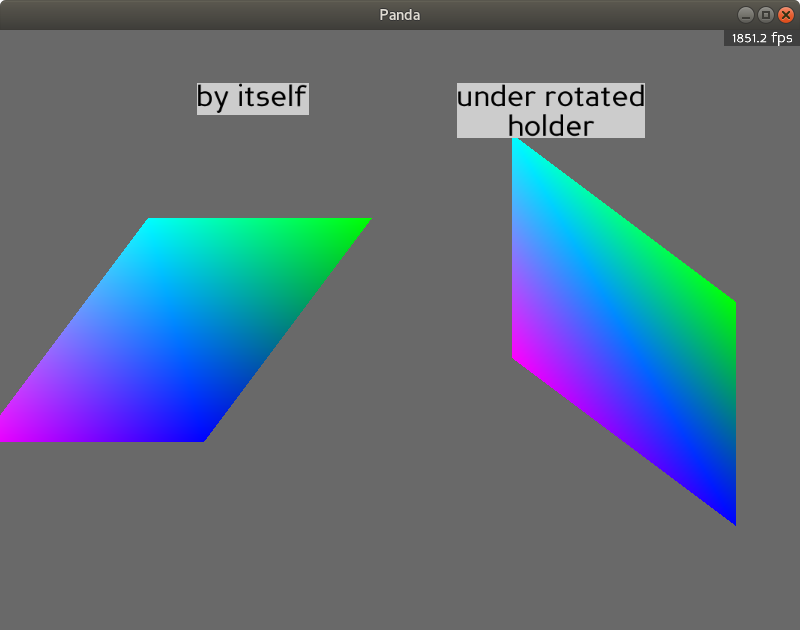
Could it have something to do with the yaw rotation applied to the fences? Or perhaps something to do with the order of transformations applied to the fence segments.

I am sorry I was not able to reply sooner, but another way to approach the original problem is to consider that a 3x3 transformation matrix is composed of three X, Y, Z basis vectors, and the xyz coordinates of the model are essentially weightings of these vectors to produce the transformed position. If the fence model goes along the X axis, this means you could compose a matrix like so:

\begin{bmatrix} 1 & 0 & \frac{z}{w} \\ 0 & 1 & 0 \\ 0 & 0 & 1 \\ \end{bmatrix}

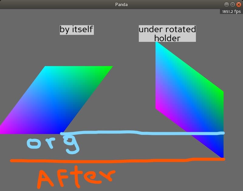
…where z is the amount by which to lift the fence (relative to the origin of the fence) and w is the width of the fence. This means that the local z coordinate of a given position in the model will be increased by this factor of the local x coordinate.

Here is a small sample.

from panda3d.core import *
from direct.directbase import TestStart

base.cam.set_y(-150)

# Fence segments are 30 units wide in x, 15 units high in z
cm = CardMaker('card')
cm.set_frame(0, 30, 0, 15)

card1 = render.attach_new_node(cm.generate())
card1.set_color((1, 0, 0, 1))
card1.set_mat(Mat4(Mat3(
    # Next fence has z of 10, so the right edge of this is skewed up by 10
    1, 0, 10 / 30,
    0, 1, 0,
    0, 0, 1,
), card1.get_pos()))

card2 = render.attach_new_node(cm.generate())
card2.set_color((0, 1, 0, 1))
card2.set_pos(30, 0, 10)
card2.set_mat(Mat4(Mat3(
    # Next fence has z of -10, this one has z of 10,
    # so the right edge of this one is skewed down by 20
    1, 0, -20 / 30,
    0, 1, 0,
    0, 0, 1,
), card2.get_pos()))

card3 = render.attach_new_node(cm.generate())
card3.set_color((0, 0, 1, 1))
card3.set_pos(60, 0, -10)

base.run()
1 Like

Thank you so much, But what if the fence goes along not just the X-axis what about Y or even XY?