Math impaired newbie need help with AR

Hi, i would like to do some AR with markers.
I will try to explain what i have and what i want.

Currently, i am detecting an Aruco Marker in an image.

I would like to have that marker serve as a reference to place and orient everything in my panda 3D project.

Since OpenCV know where the marker is relative to the real camera, i’m guessing i have to use that to position the panda3D camera so that the origin of the panda3D wolrd is on top of the marker ?

I looked at these :

but i don’t know how to use matrices and what math voodoo to do in order to get this result :

I guessing i have to use the values from here :

rVec, tVec, _ = aruco.estimatePoseSingleMarkers(
            marker_corners, MARKER_SIZE, cam_mat, dist_coef)

Any help would be greatly appreciated.

I think i solved the rotation part of the math but i have a new problem, i changed how i displayed the background to have it parented to render2d to have the correct aspect ratio and now the background is rendered in front of the 3d model.

I tried this :

self.bgCamImageObj = OnscreenImage(image='cap_esp6.jpg', pos=(0,0, 0), parent=self.render2d, scale=1)
        self.cam2dp.node().getDisplayRegion(0).setSort(-20)

and this :

title_screen = DirectFrame(image=('cap_esp6.jpg'), pos=( 1,0, 0), sortOrder=(-20))
        title_screen.reparentTo(self.render2d)

also tried this :

self.bgCamImageObj.setBin("fixed", -20)
self.scene.setBin("fixed", 1)
self.scene.setDepthTest(False)
self.scene.setDepthWrite(False)

but i always get the background image in front of the model so i only see the background.

Indeed, I think that the “render2d” and “aspect2d” nodes are rendered after the “render” node, and are rendered without any depth-testing, and as a result should always appear “in front of” the 3D scene.

So what I’d suggest then is this:

First, in order to have your backdrop stand behind everything else, I’d suggest parenting your backdrop-node to “render”, then placing it in the “background” culling-bin and disabling depth-writing for it.

This should cause it to be rendered before everything else in the scene (unless you have other things in the “background” bin, of course), and to render without affecting the depth-buffer. As a result, the 3D scene should render “in front of” it.

Second, in order to give your card the appropriate dimensions, I’d suggest accessing in the dimensions of your image (the “PNMImageHeader” class may help with this) and then scaling your quad accordingly.

The backdrop node might then be placed at an appropriate distance from the camera, with appropriate additional scaling to fit the camera-view.

This should, I think, produce the appropriate effect.

(Of course, if the camera moves, then you might want to parent the backdrop instead to the camera itself.)

Thank you for your time @Thaumaturge

So, folowing what you said i tried a few thing and the next code blocks are equivalent except for the origin of the card.

cm = CardMaker('card')
card = self.camera.attachNewNode(cm.generate())
card.setPos(-0.5,2,-0.5)
tex = self.loader.loadTexture('cap_esp6.jpg')
card.setTexture(tex)
card.setBin("background", -20)
card.setDepthWrite(False)
self.bgCamImageObj = OnscreenImage(image='cap_esp6.jpg', pos(0,2,0),parent=self.camera,scale=0.5)
self.bgCamImageObj.setBin("background", -20)
self.bgCamImageObj.setDepthWrite(False)

I use winProperties.setSize(800, 600)
My image is 800*600 too for convenience.

The result is this :

The ratio is 1:1 instead of 4:3 and the image is too small.

I have to put the second number of set pos to at least 2 or i don’t see the image.

If i try this :

self.bgCamImageObj.setX(800)
self.bgCamImageObj.setX(600)
# Or this
card.setX(800)
card.setX(600)

I don’t see the background anymore.

How can i get it to have the correct size and aspect ratio ( same as window in this case ) ?

It’s my pleasure. :slight_smile:

CardMaker by default places the origin of the card at the bottom-left (if I recall correctly)–hence the difference in placement.

However, this can be changed via a call to CardMaker’s “setFrame” methods. For that, see the API, starting here:
https://docs.panda3d.org/1.10/python/reference/panda3d.core.CardMaker#panda3d.core.CardMaker.setFrame

Indeed: you’ve set the aspect ratio of the window, but not of the card. That’s what I meant when I referred to scaling the quad (i.e. card) accordingly: by scaling the card non-uniformly–i.e. with different scaling factors for its width and height–we can alter the aspect ratio of the card.

Once again, scaling the card should help, I believe. The trick is to determine exactly how much to scale it…

If your window will never change aspect ratio, then the can perhaps just experiment with scaling-factors until you get it to pretty much fit.

If, however, you do intend to allow the window to change aspect ratio, then things get a little more complicated. I’m rather tired as I type this, so I fear that I’ll leave that for another to attend to, for now at least.

(Well, one way might be to use some camera-related methods to find the world-space positions of the left, right, top, and bottom of the screen at a distance equal to the placement of your card, and to then calculate from those the scale to apply. But there might be a simpler way, so I’ll hold off on elaborating on that approach.)

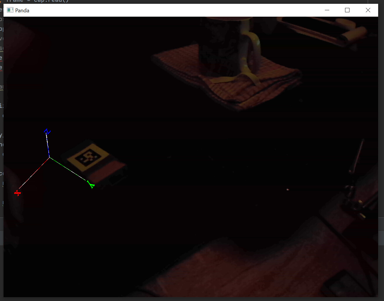
By default, I believe, objects are located at a world-position of (0, 0, 0)–and this includes the camera. As a result, the card and the camera are initially at the same location, and the camera “can’t see” the card.

Now, the camera by default points down the y-axis (the y-value being the second number in “setPos”), and thus placing the card a little distance ahead on that axis places it “in front of” the camera, allowing the camera to “see” it.

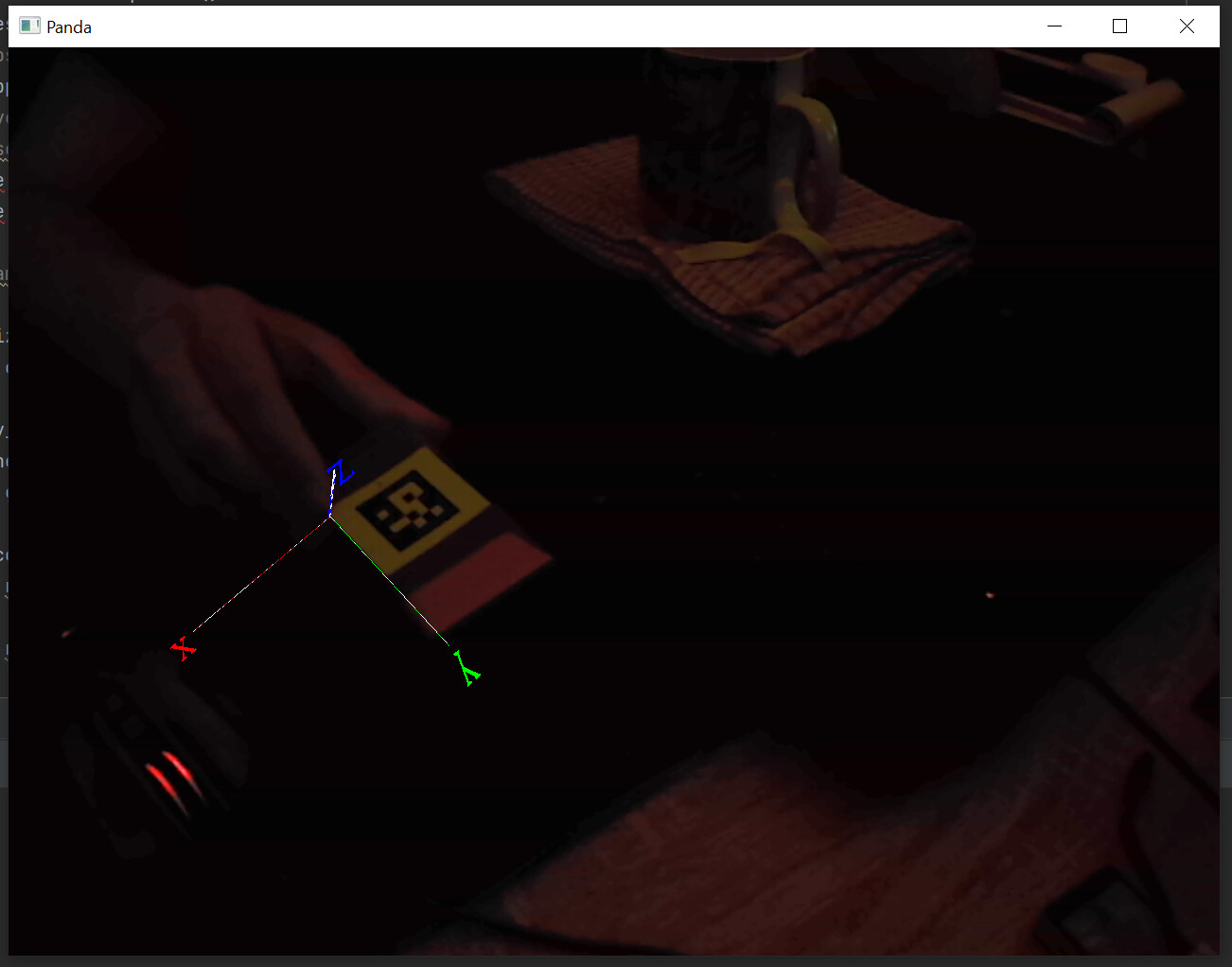
In short, this is I believe because you’re placing the object far to the right–well beyond the view of the camera.

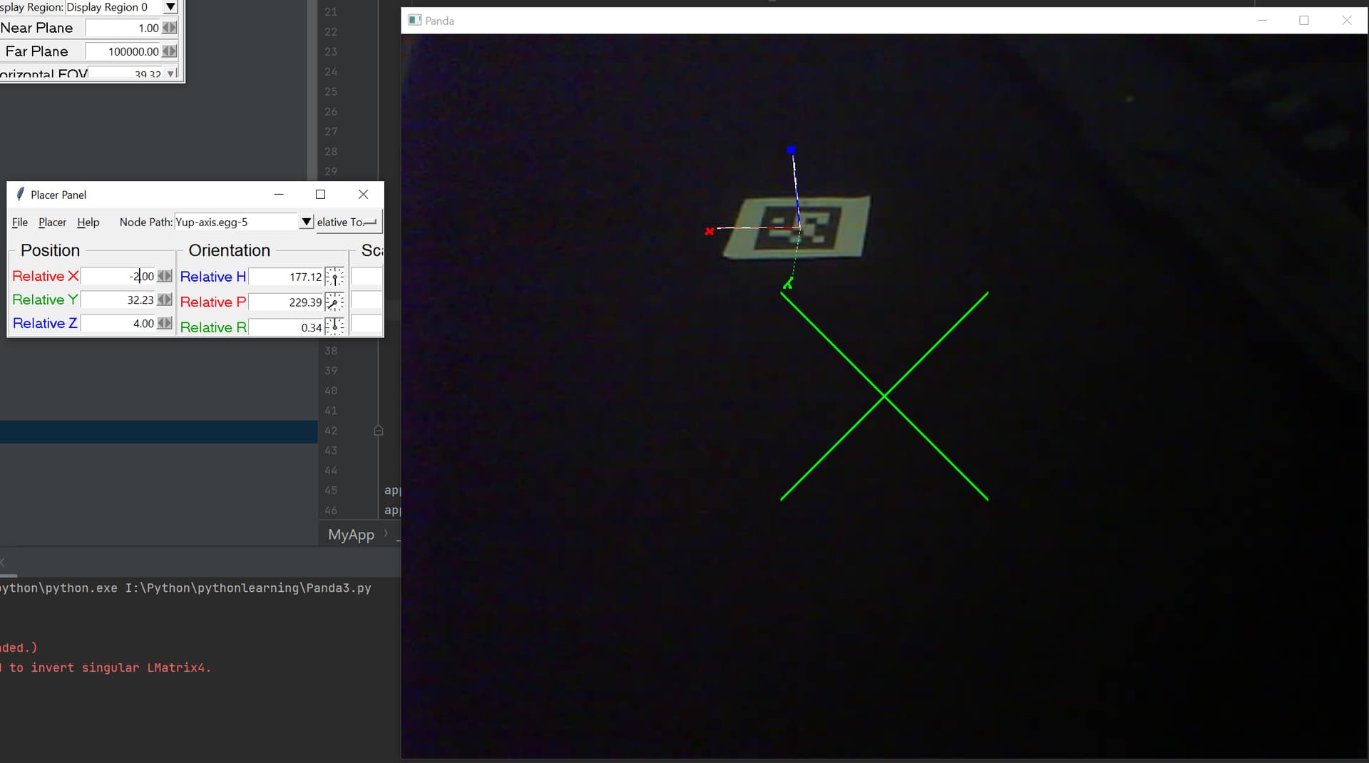
In short, when you set the position of an object that’s attached to render (or indeed, to render2d or aspect2d), its new position is given in “world units”, not in pixels.

Quite how far a “world unit” converts to on the screen depends on a few specifics, including: which of render, render2d, or aspect2d is being used; if applicable, the setup of your camera; and, if applicable, how far away from the camera the object is.

But for a simple analogy, think of it this way:

In your code, you placed the object at a position of 2 world-units ahead of the camera on the y-axis (by setting the second number in “setPos” to “2”). So, by way of comparison, consider a scenario in which you’ve placed some object 2 metres (or feet, if you prefer) in front of yourself.

Now, imagine that, without moving or turning yourself, you then alter the object’s position to be, not just 2 metres (or feet) in front of you, but also 800 metres (or feet) to your right (equivalent in this scenario to placing your object at a position of 800 on the x-axis, via a call to “setX(800)”). In most cases this will, I daresay, result in the object being so far to your right that it will no longer be in view!

Now, there is some nuance to this that I’m glossing over, but as a starting point, the above analogy might, I hope, be illustrative of why the object disappears.

1 Like

Thanks again @Thaumaturge.

I thought that

card.setX(800)

was for setting the width of the card (rookie mistake).

So what i did is :

cm = CardMaker('card')
cm.setFrame(-1, 1, -1, 1)
card = self.camera.attachNewNode(cm.generate())

card.setPos(0, 2.8, 0)
tex = self.loader.loadTexture('cap_esp6.jpg')
card.setTexture(tex)

card.setScale(1, 0, 0.75)
card.setBin("background", -20)
card.setDepthWrite(False)
card.setPos(0, 2.8, 0)

was found throught trial and errors.

card.setScale(1, 0, 0.75)

is to have an aspect ratio of 4:3 ( 3/4 = 0.75 )

I now have an image with the correct size and ratio that cover my window

My last problem is to fix the translation.
When i use the numbers given to me by the marker detection ( tVec ) the object does not line up with the marker.

rVec, tVec, _ = aruco.estimatePoseSingleMarkers(
            marker_corners, MARKER_SIZE, cam_mat, dist_coef
        )

tVec give me 3 numbers which seems to be x,y,z distance from the center of the camera.

But when i use them with setPos() the result is what you saw in the image.

I will go to the opencv forum to ask for help but if anyone has any idea, i’m all ears.

1 Like

Well done on getting it working! :slight_smile:

Hmm… I’m not familiar with OpenCV, but one guess might be that it doesn’t use the same coordinate system as does Panda.

For example, it may be that they use “y” where we use “z” and vice versa.

In fact, based on a quick search of the forum, it does look like that’s at least one problem. See the following post, in which the original poster seems to have figured out translation, but not rotation–the opposite of your problem:

The values i have are from tVec are -3.31451679 -5.09411436 32.23228801

When i do this

self.scene.setPos(-3.3145, 32.2322, 5.094)

I have the above result.

By trying some values with the .place() i get this

Since my marker is close to the center i guessed that the value 32 must be how far it is so i kept it but the -2 and 4 puzzle me.

Hmm… Could it be that your marker’s origin-point isn’t where you expect it to be…?

Otherwise, I don’t know offhand, I’m afraid! Perhaps another will have further ideas. :/

I think i have found a lead, i noticed some things :

If i move my marker closer to the center of the image, the alignement get better.


It is like i have a “distortion” in my translation coordinates.

There is an Ogre 3d example that does what im trying to do with Panda3D here :

(ogre/opencv_aruco.py at master · OGRECave/ogre · GitHub)

I can make that code work perfectly and i tried to see what i could change and what effect it had.

I managed to make a similar behavior happen in Ogre by commenting this method in the Ogre Example :

def set_camera_intrinsics(cam, K, imsize):
    cam.setAspectRatio(imsize[0]/imsize[1])

    zNear = cam.getNearClipDistance()
    top = zNear * K[1, 2] / K[1, 1]
    left = -zNear * K[0, 2] / K[0, 0]
    right = zNear * (imsize[0] - K[0, 2]) / K[0, 0]
    bottom = -zNear * (imsize[1] - K[1, 2]) / K[1, 1]

    cam.setFrustumExtents(left, right, top, bottom)

    fovy = math.atan2(K[1, 2], K[1, 1]) + math.atan2(imsize[1] - K[1, 2], K[1, 1])
    cam.setFOVy(fovy)

It take the camera, and two other parameters :

imsize = (640, 480)
K = cv2.getDefaultNewCameraMatrix(np.diag([640,480, 1]), imsize, True)

and it changes the fulcrum and the fov of the camera.

I’m trying to change the fulcrum of the camera in panda but nothing give me the result i want.

I tried to debug the Ogre example to get the values to put in the fulcrum/fov of panda but i can only get a far away small distorted image.

I will take more pics of the values in Ogre and will comment the camera functions in the hope that someone can help.

Hmm… I’m not sure that that’s all that unexpected: after all, if the problem is, say, a scaling factor somewhere, then its effect will naturally be greater when dealing with greater numbers–i.e. numbers further from zero, and thus from the origin.

For example, let’s say that, somewhere in your setup, you have a scaling factor of 1.3 sneaking in. In that case, the coordinates (0, 0) would end up as… well, as (0, 0), because 0 multiplied by anything is still 0. The coordinates (1, 0) would end up as (1.3, 0). And the coordinates (2, 0) would end up as (2.6, 0). As you can see, the coordinates are off by 0, 0.3, and 0.6–an amount that increases the further that we get from the origin.

(It’s tempting to suspect that the issue lies with the scaling factor applied to “aspect2d”–but it seems unexpected that it would affect both the x-axis and the y-axis…)

I’m not sure of what you mean by the “fulcrum” of the camera–do you mean the point about which it rotates…? Or perhaps the frustum of the camera…?

Yes, i meant frustum, not a native speaker so some mixup happen sometimes.

That’s fair! I mean only to clarify, I believe! (After all, it was entirely possible I was unaware of some camera-specific usage of the term “fulcrum”.)

So, my first instinct right now is still to suggest that perhaps there’s a scaling factor sneaking in somewhere–have you investigated in that direction?

For example, if you take your expected coordinates and multiply them by, say, 1.333, does that come close to correcting the issue? Or have you tried calling “render.ls()” (just once, after placing your marker, please note!) and looking over the output (which should go to the terminal) for a node with a scaling-factor applied?