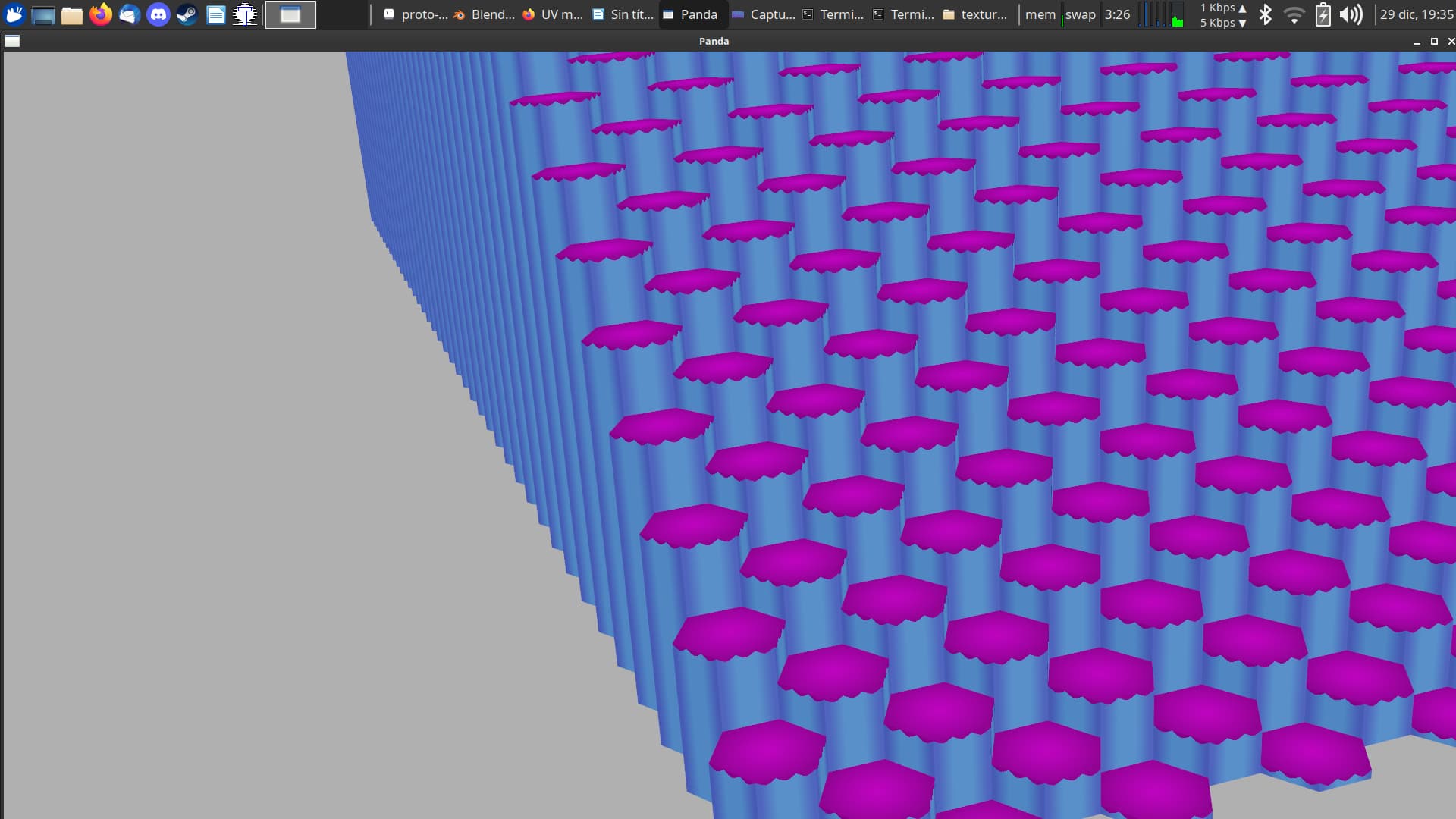
Hello there everyone. I’m new to Panda3d and mostly new to 3d in general. I am experimenting with some basic mechanics for a game I’d like to make that will procedurally generate maps by stacking hexagonal tiles. Last night, I took my basic hexagonal tile model (made in Blender 3.4, exported as a .glb, imported using panda-gltf, and shaded with panda3d-simplepbr) and replaced its generic base color materials with a UV mapped image texture. Upon running my panda3d script, all of the tiles had conspicuous pink lines between the individual tiles that weren’t there with my generic materials. After experimenting a bit, I found that I could get the problem to mostly go away if I shrank the relevant parts of the model’s UV map, leaving several pixels of the image texture out of frame. However, even leaving a significant margin, when one of the model’s faces is viewed at an angle, it appears that the model’s UV map gets stretched so that even a margin of ~7 pixels still isn’t enough. The linked screenshots show what I’m talking about. The lines/distortion get more distinct the further right you look in the first screenshot.
Is this a Panda3d issue or something that happens with any 3d rendering engine? I mean, doesn’t it break the concept of UV mapping to have your textures wiggling around by several pixels depending on angle of view? Is there something that I’ve done incorrectly? Thanks very much for any and all help/perspective!
Based on your description, this could be due to two common issues (that do indeed apply to all 3D engines).
Firstly, it could be the case that mipmapping is enabled on the textures, which causes a lower-resolution version of the texture to be used at greater distances (improving performance and filtering). But in the lower-resolution version of the texture, pixels are being averaged with neighbouring pixels, which can cause bleeding. In the most extreme case, when your object is roughly 1 pixel on screen, it will use a 1x1 version of the texture that has all pixels of the texture blended together.
By default, mipmapping is isotropic, so a lower resolution version of the texture is also used when viewing the model at an angle (ie. the texture gets blurrier). You can enable anisotropic filtering on the texture as well to improve the filtering of textures at shallow angle, at an additional performance cost.
To avoid this, it’s best that your UV coordinates go right up to the edge of the UV space if possible. If you have packed several textures into the same UV map, you could extend the image in the UV map by several pixels, and set a “max lod” level on your texture to limit the amount of filtering to be no more than the amount of boundary pixels you created in the texture. For max lod level of 0 (mipmapping disabled), you need no overlap; for level 1 you need 1 pixel of overlap and it doubles for every subsequent lod level. Note that the more you limit the mipmapping feature, the worse your textures will look when observed from very far away.
Thank you so much for your quick and thorough reply! It makes a lot of sense, so I’m optimistic that I’ll be able to address the issue now. I tried tweaking settings for the image texture in Blender, but none of the combinations have quite fixed the problem. I’d like to try the in-code route, but there’s one thing in my way: I’m not sure how to get a reference to the texture from the imported model. $NodePath.getTexture() returned None, and from the docs, it looks like this is correct behavior if a texture hasn’t been set with setTexture. Is it possible to get a reference to my texture while using the .glb format, or do I need to change to using .gltf with separate textures and apply them in code in order to access these settings?
I think that you want “findTexture”. (Especially as the texture may well be applied not on the node, but on either the geom within it, or simply on a child-node.)
@Thaumaturge That is exactly what I needed to get the texture reference, thank you!
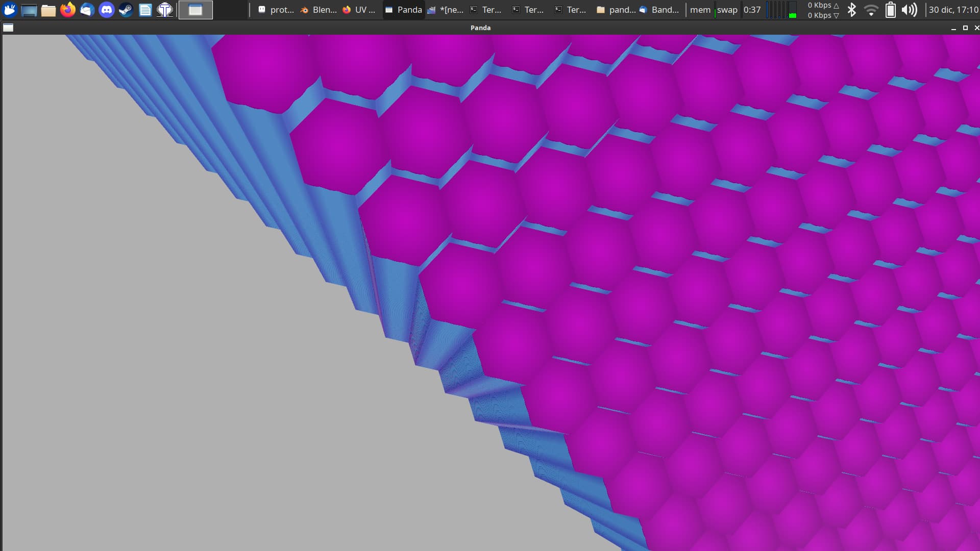
@rdb Okay, so with your advice, I’ve almost entirely eliminated the distortion. Mipmapping was definitely the relevant issue. While I did see the difference between the linear and nearest settings, it didn’t make a difference on the problem. It became very obvious as soon as I turned mipmapping off that I needed to make some changes to my texture, which was using pixel art dithering techniques that were causing distortion of their own. After correcting that, there was still a minimal but noticeable amount of “streaking,” now just a slightly darker blue instead of pink from other parts of the texture. To get the impact from this problem down to an acceptable level (still faintly there but only if you’re really looking for it), I still did need to edit my texture again to create margins of about 10 pixels on all sides, which I guess doesn’t seem to be as much of an issue as I was expecting it to be. In addition to adding the margin and retuning the UV mapping in Blender, these settings have given me the best results so far:
I did try setting texture.anisotropic_degree to 2 and 3. The results were extrremely similar, but it ultimately seems to me that leaving this set to 1 (default) was the best by a slight margin, at least in combination with the other steps I’ve taken and a few other configurations I tried.
I could see from printing the texture to the console that nothing I did implicitly changed the max lod, and I couldn’t find a method or attribute in the docs that affect this. Results are fairly acceptable now, but I would like to try this to see if it finishes the job. How can I set that value?
In any case, thanks so much for the help!
Here are the best results so far (I also changed the color of the top tiles for aesthetic reasons while I was messing with things):
If you set the mode to “linear”, you have already disabled mipmapping, so setting the LOD level is not necessary.
I do wonder if setting the mode to “nearest” will entirely eliminate the streaking. However, this would cause your textures to look pixelated.
Having to set a margin of 10 pixels without mipmapping sounds strange. Without mipmapping, I would expect you would need a margin of at most 1 pixel. Would you be willing to send me your model, perhaps?
(Alright so I’ll have to break my links up over at least 2 replies since I’m still a new user)
Having to set a margin of 10 pixels without mipmapping sounds strange
Looking at the texture again, it’s specifically 5 pixels vertical and 7 pixels horizontal. Sorry about overstating it a bit. Before actually creating additional space in my texture, I had allowed 2 pixels on all sides and still had severe streaking between tiles. It’s possible that something in between these two sizes would have sufficed, but my first attempt pretty much cleaned up the problem, so I left it at that.
I do wonder if setting the mode to “nearest” will entirely eliminate the streaking.
The results are very similar. Streaking in both screenshots occurs towards the left edge of the window:
Would you be willing to send me your model, perhaps?
Sure! (Models & textures) I’m not sure if you want my code as well, probably better for you to not have to sift through the other things going on there. But the way I have these spaced goes like this:
The x and y values don’t matter too much to this problem, but the tiles are offset in the Z axis by exactly the value of z_step. I did try reducing this slightly (z_step = dimensions[2] * 0.9) to see if maybe the positioning was the issue, but it did not solve the problem.
Sorry again for having to break this up into several replies
Edit: My other replies have apparently gotten flagged as spam for linking to imgur. I’ll try to figure out what I have to do to get my full response visible/reposted
Sorry, the posts got flagged automatically due to an overzealous anti-spam. I’ve bumped your trust level so that it hopefully doesn’t happen again.
It does really look like your textures still have filtering enabled. I would expect these results from mipmapping. It’s a little hard to see in your last screenshot since it’s JPG, but I can also see a kind of moiré pattern that results from not using mipmapping. Hmm.
I didn’t realise you were assembling your models programmatically. Perhaps you can call writeBamFile on the scene after generating it and send the resulting .bam file, so we’re sure we’re looking at the same thing. Then I can also inspect the filtering settings used on the textures.
Sorry, the posts got flagged automatically due to an overzealous anti-spam. I’ve bumped your trust level so that it hopefully doesn’t happen again.
Totally understandable, thanks so much for clearing that up!
It does really look like your textures still have filtering enabled. I would expect these results from mipmapping. It’s a little hard to see in your last screenshot since it’s JPG, but I can also see a kind of moiré pattern that results from not using mipmapping. Hmm.
Perhaps you can call writeBamFile on the scene after generating it and send the resulting .bam file, so we’re sure we’re looking at the same thing.
I’d be happy to. What specific nodepath should I call writeBamFile from? I went ahead and gave it a try on base.render, but it took a long time to write and gave me this warning:
:util(warning): Objects of type ShaderAttrib cannot be read; bam file is invalid
I assume I probably need to create a parent node to parent all the tile models to, but should I also include the lights? I have one directional light and one ambient light in the scene. Anything else I need to have in mind when calling this function?
Not sure if it helps, but print(texture) returns this information:
2d_texture proto-tile-lower-uv
  2-d, 601 x 576 pixels, each 4 bytes, srgb_alpha
  sampler wrap(u=clamp, v=clamp, w=repeat, border=0 0 0 1) filter(min=linear, mag=linear, aniso=0) lod(min=-1000, max=1000, bias=0)  1384704 bytes in ram, compression off