I’m trying to produce a specific render layering effect. It’s best described by an example:
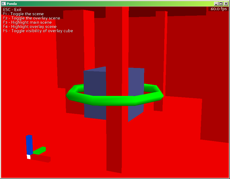
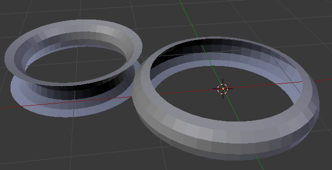
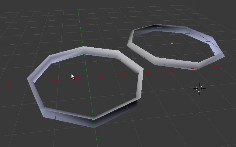
Let’s say I have three objects:
- a ‘set’, in this case a square room with some other geometry in it.
- a cube
- a torus
The cube and torus are positioned so that the cube is inside the hole of the torus, and part of the torus is spatially behind the cube, and other parts in front.
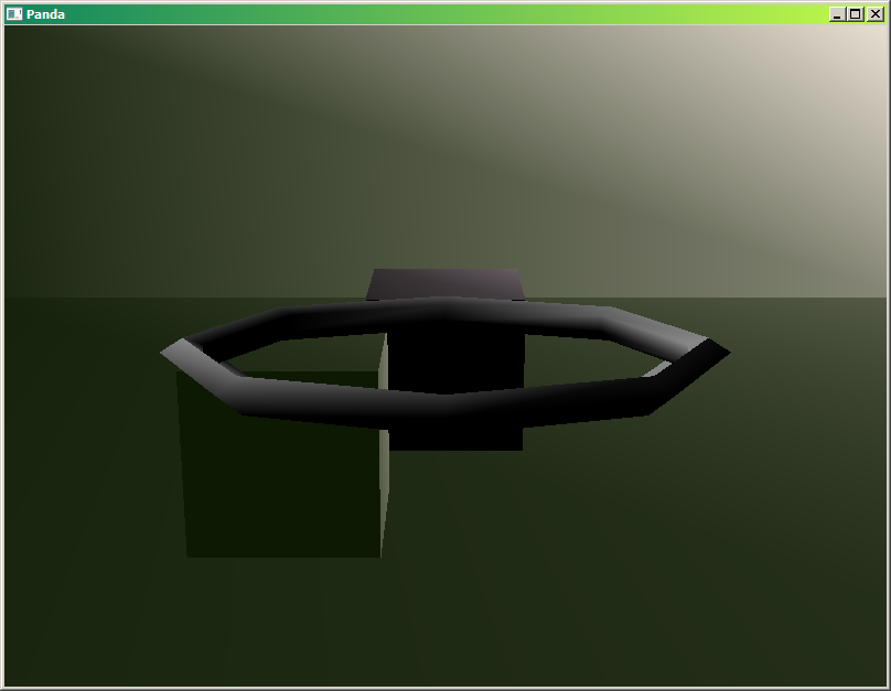
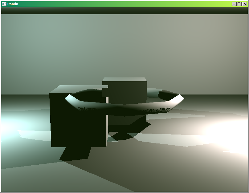
And I want them to render so that:
- the torus is always in front of the set, but equal to the cube.
- the cube is equal to the set, and equal to the cube

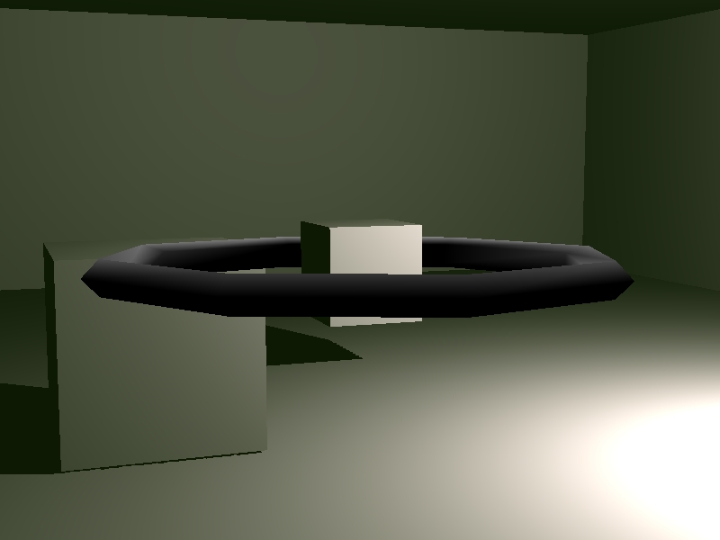
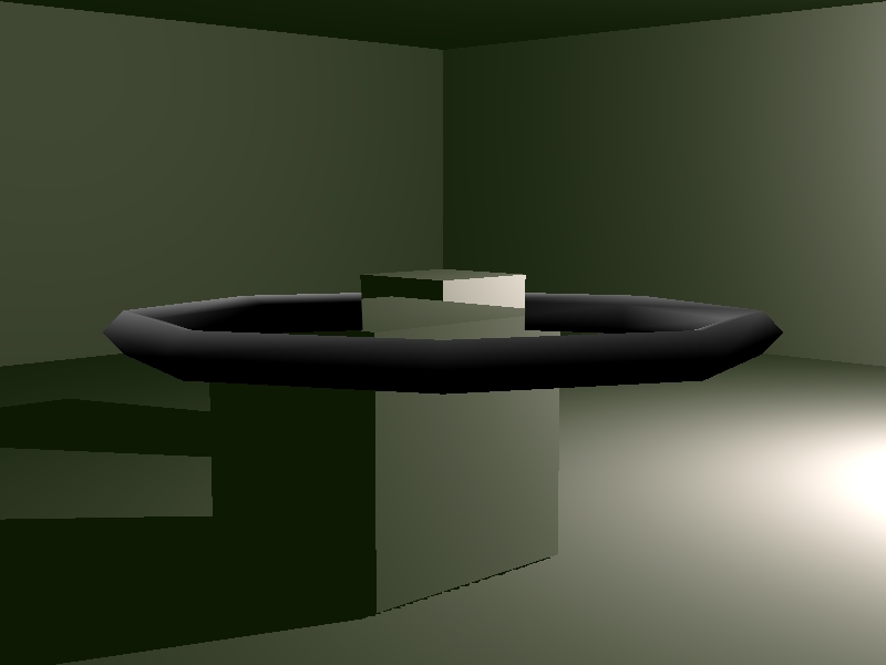
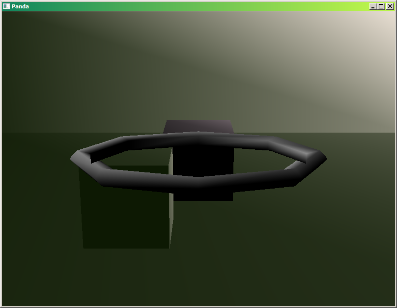
The end result should look like this: (These screenshots were photoshopped to illustrate the wanted result.)
What I’d like to know is, can I achieve this effect, and if yes, how? If there are several ways, which one would be the most efficient?
I admit, part of the difficulty here is probably my own ignorance on how rendering works in Panda3D. I’ve spent a while experimenting with display region sorting, stencil attributes, projecting renders as textures and so on, but I couldn’t make enough heads or tails of it to figure it out.
If you think you have an idea on how to do it, but need to test it first, here is a file where everything should be more or less set up as needed:
render_layering_template.zip (9.4 KB)
I’m trying to produce a specific render layering effect. It’s best described by an example:
Let’s say I have three objects:
- a ‘set’, in this case a square room with some other geometry in it.
- a cube
- a torus
The cube and torus are positioned so that the cube is inside the hole of the torus, and part of the torus is spatially behind the cube, and other parts in front.
And I want them to render so that:
- the torus is always in front of the set, but equal to the cube.
- the cube is equal to the set, and equal to the cube
The end result should look like this: (These screenshots were photoshopped to illustrate the wanted result.)
What I’d like to know is, can I achieve this effect, and if yes, how? If there are several ways, which one would be the most efficient?
I admit, part of the difficulty here is probably my own ignorance on how rendering works in Panda3D. I’ve spent a while experimenting with display region sorting, stencil attributes, projecting renders as textures and so on, but I couldn’t make enough heads or tails of it to figure it out.
If you think you have an idea on how to do it, but need to test it first, here is a file where everything should be more or less set up as needed:
render_layering_template.zip (9.4 KB)


 I was talking about it.