PointLight and node.setLightOff

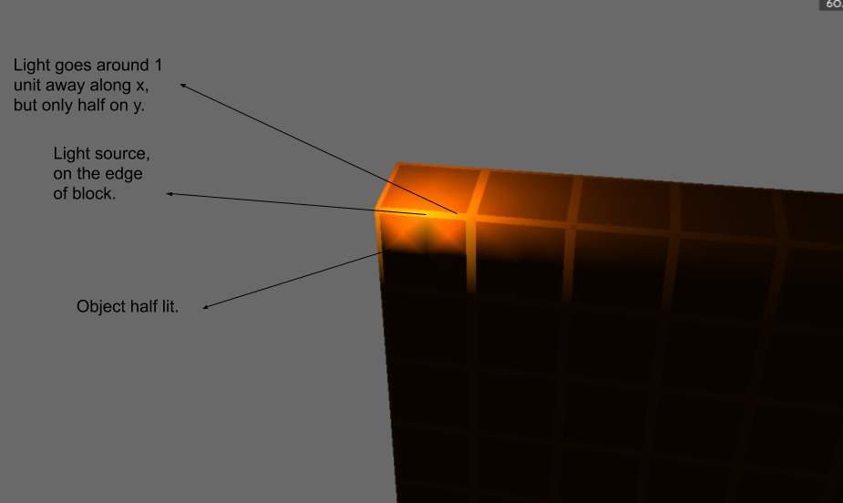
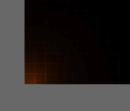
When I use the point light class, it makes a light in the scene but only one half of the scene is lit and setMaxDistance also doesn’t seem to work.

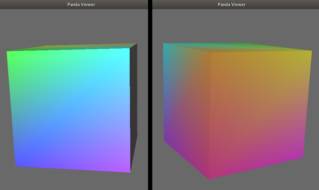
Also when i do node.setLightOff(), it just puts light on instead of making it dark.

I am trying to make a scene with blocks and a lamp in the corner. My code (i have made the showbase class, it is screen):

a = []
b = NodePath('hi')
for x in range(20):
    for y in range(20):
        a.append(screen.loader.loadModel('/d/Dirt.bam'))
        a[-1].setPosHprScale(x, y, 0, 0, 0, 0, 20, 20, 20)
        a[-1].reparentTo(b)
b.reparentTo(screen.render)
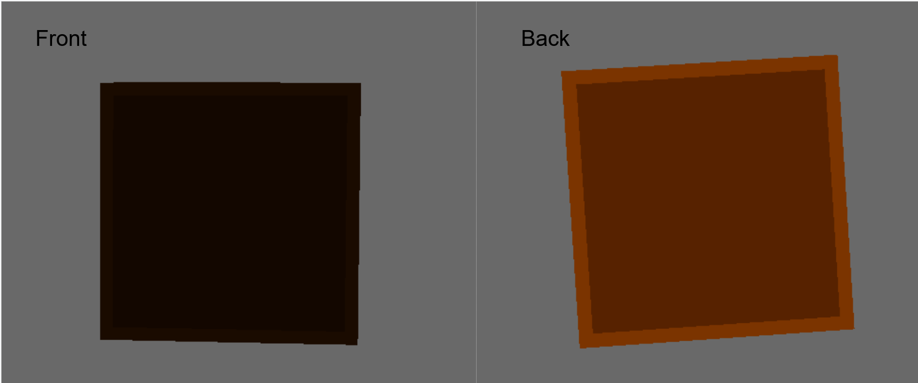
b.setLightOff()  # if i comment this, blocks appear normal, but with this line, all blocks are lit up

alight = AmbientLight('ambientLight')  # this light works
alight.setColor((0.1, 0.1, 0.1, 1))
alightNP = screen.render.attachNewNode(alight)
screen.render.setLight(alightNP)

slight = PointLight('pointLight')  # doesn't work, one half lit
slight.setColor((2, 2, 2, 1))
slight.setAttenuation((1, 0, 0))
slnp = screen.render.attachNewNode(slight)
slnp.setPos(0, 20, 0)
screen.render.setLight(slnp)

dlight = DirectionalLight('directionalLight')
dlight.setColor((1, 1, 1, 1))
dlNP = screen.render.attachNewNode(dlight)
dlNP.setHpr(0, 0, 0)
screen.render.setLight(dlNP)

screen.run()

I think that the reason for “setLightOff” producing the effect that you note is that, with no lights active, the use of lighting in rendering is disabled–that is, that the presence or absence of lights has no effect on the rendering of the objects affected. This results in them being rendered flatly, with unshaded textures and colours.

I’m not sure of why your point-light affects only part of your scene. However, I think that it’s not “setMaxDistance” that determines how far it reaches, but rather “setAttenuation”: making it reach further is a matter of finding good attenuation settings, I think.

Ok, I understood setLightOff.

And in pycharm, when you press ctrl and click on something, it goes to the source file. In this case PointLight.py. In that, going to setMaxDistance, it says attenuates light after set distance to 0. If you use setAttenuation for setting distance, then what is setMaxDistance used for.

Also if you want to increase range what would be the logic for setAttenuation.

Also wanted to add, objects in the scene are half lit only if light is touching an object, if it is not touching an object, the scene objects are black.

I’m not sure, I’m afraid.

That said, looking at the API entry for “setMaxDistance”, I note two things:

  1. It says that the method sets the light’s “sphere of influence”.
  2. It says that beyond the given distance, “the light may be attenuated to zero, if this is supported by the shader.” (Emphasis mine.)

From these points I suspect that what it does is set a distance beyond which objects are not affected by the light, and that attenuation isn’t necessarily a part of what it does; i.e. that standard attenuation is handled separately.

Furthermore, since it only mentions attenuation beyond the maximum distance, I imagine that standard attenuation still applies within that distance. This means that standard attenuation may result in the light fading to effectively-black well before that maximum distance has been reached.

That’s hard to give a concrete answer to.

Simply put, attenuation is a function, of the following form:

light-value = a / (c + l*distance-to-light + q*distance_to_light^2)

Where “a” is a constant value, “c” is the constant term of the function, “l” is the linear term of the function, and “q” is the quadratic term of the function. Thus, the higher the values of “c”, “l”, and “q”, the more quickly the light falls off, and the smaller the light’s effective radius is.

Thus it’s a matter of choosing values for “c”, “l”, and “q” such that the light isn’t attenuated too much before it reaches the extent that you want it to have.

When you call “setAttenuation”, you’re setting “c”, “l”, and “q”, I believe.

You can find out a bit more on this manual page, I think.

Ah, I think that I understand better now. My apologies! In that case, it seems that perhaps your light is too dim.

1 Like

I have attached an image describing my half lit scene.

Also in the equation

what is the value of a, and I assume light-value is the intensity of the light on object and distance_to_light is objects distance from light source. Assuming a as 1, a block 14 unit away lit at 0.1 intensity, the light has c, l, q = 0.5, 0.5, 0.012, am I correctly using the logic? Clearly (testing it), either I am wrongly applying the formula or my assumption of a = 1 is wrong.

Yes, my light was too dim.

Ah, I see. Hmm… I’m not sure of why that’s happening.

I do note that it’s primarily happening in the interior of the blocks–the strips at the edges seem to be lit differently. Furthermore, it seems to cut off at about the edge of a squarish pattern.

Is there a normal-map applied to your blocks? Perhaps that’s resulting in unexpected lighting.

Honestly, I don’t know offhand. It may well be “1”, or some other value.

Exactly, if I’m reading your correctly: the level of illumination applied to the object.

Indeed, correct. :slight_smile:

Let’s see…

With “a” of 1; “c”, “l”, and “q” of 0.5, 0.5, and 0.012, respectively; and at a distance of 14 units, we have the following (if my maths is correct):

light-value = 1 / (0.5 + 0.5*14 + 0.012*14*14)
light-value = 1 / (0.5 + 7 + 2.352)
light-value = 1 / 9.852 = 0.1015

So it looks like you’re correct: at that range, with those values, you should get an intensity of 0.1.

Do note, however, that any colour applied to the light will affect the final result, too, if I’m not much mistaken. In your case I see above that you’re assigning a colour of (2, 2, 2, 1), as a result of which I’d expect your light to be twice as bright as one might expect from the base calculation above.

I am using 3D builder (Windows), saving it as gltf and using panda3d-gltf. I think that might be the problem.

The formula doesn’t work, putting c, l, q = 0.5, 0.5, 0.012, only 2 units are lit up.

image

Thanks a lot for helping me out and sorry if I am a noob.

Possibly; I’m afraid that I’m not familiar with those tools, myself, and so I’m not in a position to really assess the possibility.

I do note that you’re scaling your boxes by 20–unless “Dirt.bam” is 0.05 units long, your boxes presumably aren’t ending up one unit along each dimension.

That said, looking at your image, it looks to me that the light is affecting more-distant boxes, just more dimly.

Running the numbers that you gave, and providing a distance of sqrt(2) (the distance from one corner of a unit square to the other), I get an expected value of ~0.81. Looking at the image, I can believe that the top-right corner of the bottom-right box is lit at an intensity of 0.81. Using a distance of sqrt(8) (the distance from one corner of a unit square to the opposite corner of the next diagonal square) I get a value of ~0.5–and again, I can believe that the relevant square in your image is lit with an intensity of 0.5.

I might suggest experimenting with different values for c, l, and q; you may find some set of values that produce the sort of lighting that you want. (I find a spreadsheet to be useful for this purpose, myself.)

It’s all right! These things can be tricky at times, I feel.

And I’m sorry that I’m not managing to provide better help!

‘Dirt.bam’ is 0.05 units, and they are all indeed 1 unit apart as i am doing setPos with each block 1 unit apart using the for loop.

for x in range(20):
    for y in range(20):
        a.append(screen.loader.loadModel('/d/Dirt.bam'))
        a[-1].setPosHprScale(x, y, 0, 0, 0, 0, 20, 20, 20)  # x and y are whole numbers and each box is 1 unit apart
        a[-1].reparentTo(b)

Indeed the formula works, and thanks for the spreadsheet idea, it has come in handy, especially because it is very hard finding a good c, l, q value.

Ok, everything works now except that the scene is half lit. The problem persists only along the Y-axis.

Ah, fair enough.

Ah, I’m glad that you’re making progress! And indeed, finding good values for the attenuation function can be tricky, I fear.

Hmm… What happens if you load “Dirt.bam” in PView, and then activate both lighting (by pressing “l”) and per-pixel shading (by pressing “p”)? What does it look like there, and how is it lit? (You may also want to centre the view on the model, especially given the model’s size; to do this, press “c”.)

Pressed ‘l’ and ‘p’, here are the results:


(Yawed 180º).

Hmm… It’s odd that the front is lit differently to the back. Do you have a normal-map applied to your model? And how does the lighting look in PView without per-pixel lighting? (That is, having pressed “l”, but not “p”.)

There are no normal maps (bumps, grooves in model) attached and the cube looks the same without per-pixel shading.

In which case, perhaps there’s a problem with the normals in your model.

By way of demonstration, here’s an image showing views of a simple model (with some colours applied to distinguish one end from another) that I made in Blender and exported via YABEE:

In this case, I only activated lighting, not per-pixel lighting; however, the results with per-pixel lighting were much the same, I believe.

Note that, whichever side is shown, it’s lit; conversely, in the case of your model, only one side is lit. Thus I suspect that the problem lies with the normals in your model.

Yes, when i use the ‘models/box’, everything works fine, so I expect it is the panda3d-gltf, thanks a lot!

1 Like

For the record, setMaxDistance is not currently respected by the default Panda3D shaders. It’s stored for the purpose of any custom shaders that might use it. Use attenuation to attenuate the light over distance.

2 Likes