From an external program I get 4 x,y,z positions representing a quad in a 3d space. I also get a stream of 3d points that are assumed to be “drawn on the quad” and save it in a 2d image. The quad in question is not a perfect rectangle with a known aspect ratio.
If it was a 2d quad it would be easy to do with PIL:
get the bounding rectangle of the quad and create a 2d image from that bounding rectangle and use the bounding rectangle’s aspect ratio as the 2d image’s aspect ratio
convert the positions of the points from the 3d space to image pixel coordinates.
But the quad being in 3d means the quad isn’t always parallel in one coordinate space and if I assume that than the generated 2d image will have pretty bad perspective distortion.
I’m guessing the way to do it is to calculate the face normal of the quad and somehow transform the quad and point coordinates with that normal but I’m lost.
As far as I know, the bounding frame for 2d depends on the camera position. Accordingly, you need to set the camera perpendicular to the polygon using the normal. It is not necessary to make calculations with a perspective, it is just a guess.
Sorry that I can’t explain this in a more clear way. This has nothing to do with render2d or generating a screenshot from panda3d. The generated image is generated by PIL, not Panda. Nor are the 3d points rendered in Panda3D for screenshot to be usable.
I’m not entirely clear on what you’re trying to do: are you attempting to colour a quad with “spots” produced by a set of points, or are you attempting to clip the view of a set of points with the quad (the quad essentially serving as a “window” to the points), or something else?
Let me get into more details while risking to make it even more complicated:
I receive 3d data from a 3d input device.
The 3d input device defines a 2d drawing plane by 4 x,y,z points in a 3d space where 2d image may be drawn. That 2d drawing plane does not have to be a perfect rectangle, it’s just a nearly perfectly planar quad.
This 3d input device then streams its position.
The goal for me in Python is to convert this quad and point stream into a PIL image.
This is where my OP comes into play.
If the 2d drawing plane in 3d space was perfectly parallel to one axis, I could just generate a PIL image from the bounding rectangle, but since the 3d input device allows to define the 2d drawing plane in any position and orientation, it’s more complicated than doing steps 1 and 2 in my OP.
So the 3D points are intended to be “spots” on the quad–the quad essentially being a “canvas” that’s being painted on–is that right? And you then want to render this quad, along with its “drawing”, from some perspective, yes?
If I have that correct:
I suppose that you could define a Plane object (see the API here), and use the “project” method to find the nearest point on your surface for each of your “drawing points”. That should allow you to employ PNMImage to place a spot at the relevant position on a texture, which would then be applied to the quad, producing the “drawing”. This could then be rendered as per usual, from whatever perspective is appropriate.
Thanks Thaumaturge.
You almost got it all right.
The thing is I don’t want to render the virtual “canvas” (the drawing plane) and the 3d points, I think that will be wasted resources. All I want for Panda to do is display the 2d image result as a texture in 2d.
So ideally I’d want to do the 3d point 3d position -> 2d pixel position conversion in code without rendering and just storing values in a PIL (or PNMIMage, doesn’t matter) image without wasting resources rendering what’s going on in 3d. Does this make sense?
Of course, displaying the image involves some sort of rendering, unless you go through some library other than Panda–the basic way of putting a 2D image on-screen in Panda (handled in the background when using things like OnscreenImage) is to create a quad, apply the image as a texture, and then render that, I believe.
But indeed, you needn’t render the actual arbitrary quad onto which you’re “painting”.
I think that what I suggested above should work–you could just skip rendering by not attaching your quad to the scene-graph. It also occurs to me that you might want to validate your projected “drawing points”, checking that they fall within your quad; if I recall correctly, there’s a technique for this that involves comparing cross products–some searching should turn it up, I think.
I didn’t mean rendering the image, I meant rendering of the 3d points and quad (the canvas) in 3d space and my desire to avoid that.
Even if not rendering but using the SceneGraph I’d imagine there would be some overhead, although much less, so worth a shot.
However I’m not entirely sure how your proposed approach would work. Checking the API the Plane object seems to be 1) infinitely big and 2) needs a vector to define its orientation. In my case I don’t have the orientation (the normal vector) and the quad is made up of 4 xyz vertices. Maybe there’s a way to get the normal of a face in Panda3D but I don’t recall. Besides that there’s also the issue of the Plane being infinitely big. I don’t quite follow your proposal and how it would account for these two points, can you please elaborate a bit more?
Thank you.
Hmm… There might be some way, but I’d suggest trying the 3D approach first as the “simple solution”, and looking for other ways if it does in fact turn out to be too slow.
Sure!
This is what I was alluding to when I spoke of “validating” your projected points. In short, you would generate your projected points using the Plane object, then check whether they lie within the bounds of your quad.
As I said before, there’s a means of doing this that involves cross-products, if I recall correctly; while I’m not confident of remembering it offhand and am too tired to want to work it out right now, I seem to recall that it’s a fairly well-known technique, and thus should turn up in a web-search. (I might suggest keywords like “point within convex polygon”, or something like that.)
You should be able to define that from your points, if I’m not much mistaken.
One way might be to define two vectors, each being the result of subtracting the position of one point in the quad from the position of another–thus giving two vectors that each give the direction from one of your quad’s points to another. The cross-product of these two vectors should give you a normal vector for your plane, I believe.
As I said, I’m tired, so I fear that the above may not be clear. Let me try to illustrate for clarity’s sake:
There is a Plane constructor that takes 3 points instead of a normal vector and one point. So you can just pass 3 of the 4 points of your quad into that constructor.
It seems to me that all you need is a matrix to transform each of your streamed points from 3D space to a 2D space (let’s say the XZ-plane). What could probably work is to use this look_at function to compute the (inverse) orientation component of that matrix, and taking the negative coordinates of what you consider to be the “origin” point of your quad as the translation component.
So first you need the vectors to use as the “forward” and “up” vectors in the local space of your quad. The forward vector would be the normal to the quad’s plane, while the up-vector would point from the origin to another of the four quad corner points (exactly what point that is, is again something you will have to decide).
The code would look something like this (P1, P2, P3 and P4 are given in clockwise order; P1 is chosen as the origin point):
The resulting p_2d points should have a Y-value of (nearly) zero.
Depending on your choice of point order, origin point and point “above” that origin (to form the up-vector), the resulting image may appear mirrored/flipped.
I’m not sure if we have the same idea here. What 2D space are you referring to?
What I’d imagine I would need here is to convert from the positions of the streamed points from “global” 3d space to the local 3d space of the quad, where the Z axis would be equal to 0 on the quad and oriented how the face normal vector is oriented, and I could use that to determine if the streamed points are “on” the quad or not. I’d still want the coordinate spaces of the points not “on” the quad also converted to the quad’s local space for debugging purposes.
Maybe you mean the same thing, maybe not, I’m not sure. Let me know.
I’m not familiar with these concepts but I’ trying to follow along.
I’d want the bottom-left vertex of the quad to be the origin.
Again I’m not very experienced with these concepts but are you sure you don’t mean the opposite, that the forward vector points from one vertex to another (in my case bottom-left to bottom-right) to define the Y axis orientation while the Up vector would be normal to the quad’s plane? I guess this may depend on whether the 3d engine is Y-Up or Z-Up?
The code would look something like this (P1, P2, P3 and P4 are given in clockwise order; P1 is chosen as the origin point):
The resulting p_2d points should have a Y-value of (nearly) zero.
Thanks for the code. Again based on the first part of your post I quoted, I’m not sure this does what I want. It depends on what “2d space” you’re referring to.
Yes I’m pretty sure we’re on the same quad page.
The 2D space I’m referring to is just the coordinate plane (not to be confused with Panda’s Plane object) defined by the world X- and Z-axes. You can compare this to the coordinate system used by DirectGUI; the Y-coordinate of a widget is mostly ignored/zero.
That’s pretty much what my code does, apart from switching the meaning of the local Y- and Z-axes.
The reason I chose the XZ-plane instead of the commonly-used XY-plane is that the default “forward direction” in Panda is along the positive Y-axis, which is along the normal to the XZ-plane. So it is easiest to compare the orientation of the quad with the one of that plane.
But if that’s too counter-intuitive, fair enough, all that is needed then is to multiply the transformation matrix with an additional rotation matrix (describing a pitch of -90 degrees).
Don’t worry, that third coordinate won’t just disappear, so you can still check its value to determine the point’s offset from the plane.
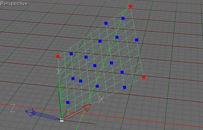
Here are some pictures so I wouldn’t have to write a thousand words :
The first image shows the quad (the green rectangular wireframe) with an arbitrary position and orientation, relative to “world space”, as represented by the grid and its red and green X- and Y-axis lines.
All of the thick points lie on the quad; the white one is the origin point, while the red ones are the 3 other corner points of the quad.
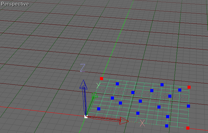
The second image shows the quad transformed such that its local axes are aligned with the corresponding world axes and its origin is placed at the world origin.
And that’s the purpose of my code: to transform the points in such a way that they end up in a world-coordinate plane, with one coordinate being the offset to that plane.
Now that I’ve tested my code, I noticed that the origin has to be subtracted from the 2nd corner point instead of the 4th, so I’ve changed that and now it all works as (I) expected.
As a speed optimization, I’ve added the point coordinates to a GeomVertexData, and simply call its transform_vertices method to transform all of its vertices at once. As a further optimization, I use memoryviews to access the vertex data.
Here is a complete, working example:
from panda3d.core import *
from direct.showbase.ShowBase import ShowBase
import array


class MyApp(ShowBase):

    def __init__(self):

        ShowBase.__init__(self)
        points = (
            # corner points of quad
            Point3(-1.64410, -3.10906, 1.25042),  # origin point
            Point3(-4.02308, 4.06295, 5.36958),
            Point3(5.13231, 2.66174, 13.09689),
            Point3(7.51130, -4.51027, 8.97772),
            # points on/near quad
            Point3(-1.20436, -1.81478, 2.84698),
            Point3(-1.95411, 3.06551, 6.50312),
            Point3(-1.00251, 0.19671, 4.85546),
            Point3(0.15092, -0.66062, 5.21628),
            Point3(0.35277, 1.35086, 7.22476),
            Point3(1.74411, -0.22366, 7.17365),
            Point3(2.45780, -2.37527, 5.93792),
            Point3(1.94595, 1.78782, 9.18214),
            Point3(2.38570, 3.08210, 10.77870),
            Point3(3.81309, -1.22110, 8.30720),
            Point3(4.01493, 0.79038, 10.31568),
            Point3(5.20442, -2.79562, 8.25611),
            Point3(5.68022, -4.23003, 7.43227),
            Point3(4.45467, 2.08465, 11.91225),
            Point3(6.32181, -0.92427, 11.03731)
        )
        p1, p2, p3 = points[:3]
        plane = Plane(p1, p2, p3)
        forward_vec = plane.get_normal()
        up_vec = p2 - p1
        rotate_mat = Mat4()
        look_at(rotate_mat, forward_vec, up_vec)
        rotate_mat.invert_in_place()
        # get the quad points into the XY-plane instead of the XZ-plane
        rotate_mat *= Mat4.rotate_mat(-90., Vec3.right())
        translate_mat = Mat4.translate_mat(-p1)
        mat = translate_mat * rotate_mat
        # to speed up calculations, the point coordinates can be added to
        # a GeomVertexData, which can transform all of its vertices at once
        vertex_format = GeomVertexFormat.get_v3()
        vertex_data = GeomVertexData("data", vertex_format, Geom.UH_dynamic)
        vertex_data.unclean_set_num_rows(len(points))
        pos_view = memoryview(vertex_data.modify_array(0)).cast("B").cast("f")
        coordinates = array.array("f", [c for p in points for c in p])
        pos_view[:] = coordinates
        vertex_data.transform_vertices(mat)
        # retrieve the transformed points from a fresh memoryview
        pos_view = memoryview(vertex_data.get_array(0)).cast("B").cast("f")

        for i in range(len(points)):
            p_2d = Point3(*pos_view[i*3:i*3+3])
            print(p_2d)


app = MyApp()
app.run()
These are the expected output coordinates of the points, as found using my modelling program: