Panda3D Studio!

Yes, indeed. Especially in this case there really should to be 3 different vertices at a corner, because each of the 3 sides that come together in that corner has a different lighting normal (unless the box should appear to be entirely smooth, which is not usually desired). Since a vertex can have only one normal, 3 vertices have to be used.
Apart from the normals, the texturing across the corners of a box is usually not continuous, so there also have to be different vertices for different UVs.

Well, non-uniformly scaling just means that the dimensions get multiplied by a different amount along the different axes. (If a polygon is rotated before non-uniform scaling, this will also introduce shearing/skewing.) Thatā€™s still something different than creating an irregular polyhedron, I think.

This is pretty good. I canā€™t believe I never saw it before.

Thereā€™s one use case where this is the only tool freely available and capable, as far as I could find. Thatā€™s making grass with correct normals. I couldnā€™t find anyway to get Blender to do it. So, to do it, you make two rectangles (billboards) and point the normals out like they are on the treeā€™s leaves here: https://polycount.com/discussion/125920/correct-vertex-normals-for-foliage Thatā€™s easy enough. The problem comes in that you need the normals on the bottom to point vertically. Otherwise you end up with floating grass like the top one here: https://forums.unrealengine.com/development-discussion/rendering/36573-grass-shading-issue With the bottom normals virtical (like the normals for the surface the grass is sitting on) the shading can blend into the ground at the bottom. Anyways, Blender could make the normals face out, but thereā€™s no way to make a subset do something else.

This was part of a larger article on foliage, but I can no longer find the article.

There is a way in Blender, I think: you can use a ā€œNormal Editā€ modifier, specify ā€œParallel Normalsā€, and place the target-object directly above the origin of the grass-object. Iā€™ve done something similar for matching the normals of patches of city-streets, but I think that it should work for grass, too.

(I think that I recall that the way that Iā€™ve handled grass normals myself, however, was to encode normal-information in vertex-colours, and to use a custom shader to interpret the result. For one thing, this may allow one to encode variations in normal from the surface below (via a ray-cast), thus allowing for a better match and some variety in the resultant colouring.)

Glad to hear my project was of use to you :slight_smile: .

Would you mind if you included screenshots of you doing this in Panda3d Studio? Iā€™m just curious to see how you did it. Iā€™m still pretty new at 3d modeling.

MAJOR UPDATE!

Apart from a good number of small bugfixes and some general code clean-up, some exciting new features have found their way into this project :slight_smile: .

First off, as suggested by @Jb_Skaggs, any components of the GUI (toolbars, menu bar, status bar and/or control panels) can now be hidden. Just uncheck the corresponding menu items in Options->Customize->GUI->Show. Ah, but what if you hide the menu bar and want to make further adjustments? No worries, you can Control-right-click in the viewport to bring up a main context menu that contains all menus from the menu bar as submenus (whenever you hide the menu bar, a message dialog will pop up to remind you of this). And there are also hotkeys to hide (Control+Shift+X) or show (Control+Alt+X) all components at once.

Secondly, a couple of very powerful features are snapping and alignment. These are accessible through the same toolbar, as they are somewhat related. These are not only available for objects, but also for the current reference coordinate system and center of transforms.

Snapping is available for objects (when transforming or creating them), for the reference coordinate system and for the center of transforms.

  • For transformations, the default is to snap to increments (e.g. angles when rotating), but you can also snap a first point (e.g transform center, object pivot, vertex or polygon center) to a second point.
  • When you want to create an object, you can set different snap options for each creation phase. For example, when you create a cone, you might want its origin to snap to a grid point at creation start, but snap to a vertex of some other model when drawing out the base cap. Then you could again snap to a grid point to fix the height (in this case, a different grid plane will automatically be shown to make this possible) and finally you could use an incremental offset to draw out the top cap.

Alignment is available for objects and for the reference coordinate system (represented by the grid).
Itā€™s possible to align to the current view, to another object, to a point/normal on the surface of a model and you can even aim a local object axis at a specific point of another object.

In object creation mode, the construction grid can temporarily be auto-aligned with the surface of a model of your choice; the newly created object will have its pivot at the point you clicked and its local Z-axis will be aligned with the surface normal in that point.

To further assist with object creation, you can now pause any creation phase by going into navigation mode to get a better view and make the rest of the creation process more comfortable.
It is even possible now to skip any (Tab key) or all (Enter key) creation phases entirely, in which case the current defaults for e.g. base size, radius, height etc. will be used to auto-complete the object.

As mentioned above, alignment/snapping can be applied to the reference coordinate system and transform center, but custom transform values can also be set for them using a dialog, and these can be stored and recalled at any time for even more control.

And now for something entirely different.

One of the most useful mesh modelling tools is undoubtedly the ability to extrude polygons.
For those of you who have (im)patiently been waiting for such a tool to appear in this project, I have good news: the polygon extrusion and inset tool has arrived :smiley: !

Although the results might not always be what you wanted/expected, Iā€™m still quite pleased with what I have accomplished:

  • there do not seem to be any bugs;
  • the geometry shader I implemented to preview the results seems to work very well;
  • concave polygons and regions are inset correctly;
  • holes and self-intersecting borders of selected regions are not a problem.

For the geometry shader, Iā€™m happy to have found a way to prevent it from generating unwanted internal polygons (extruded from diagonals and shared edges); even though itā€™s just a preview, that would have looked really bad.

Here are some pics.

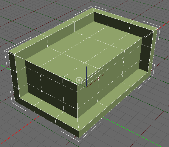
A box with the tool applied to it, twice in succession:

  1. inset without extrusion;
  2. negative extrusion (intrusion?) without inset:

Extruded%20box

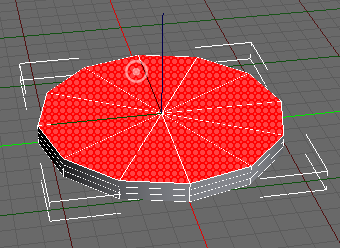
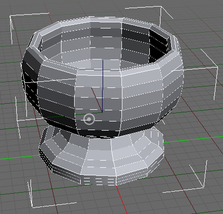
A goblet, extruded from a flat cylinder:
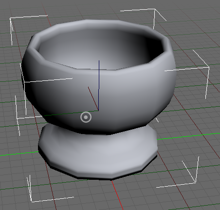
Extruded%20goblet%20-%20base%20cylinder Extruded%20goblet%20-%20unsmoothed%20wire Extruded%20goblet%20-%20smoothed

Happy modelling :slight_smile: !

2 Likes

As a follow-up to the previous post, Iā€™m happy to announce the addition of two more tools:

  • doubleside any contiguous regions of polygons;
  • solidify the entire surface of a model (based on the former tool and the extrusion tool):
    Before solidification
    After solidification

Enjoy :slight_smile: !

1 Like

I wonder what makes it so innovative in relation to 3D editors? It would be better to create a plugin for level design, for example, in a blender. I mean editing geometry, it seems to me a waste of time on code.
Of course, something like an editor for roads and intersections will be useful, or advanced brushes for relief.

As a heads-up to the users of this project, Iā€™d like to notify you that the next release (v1.0.0) will be backwards incompatible with the current version (which Iā€™ve now tagged as v0.9.0), so you are strongly advised to finish your current projects and export the models you have created before upgrading to v1.0.0 when it gets released.

Most of the changes will be ā€œunder the hoodā€, but there will be a new feature that you might find interesting: Catmull-Clark subdivision surfaces :slight_smile: . For those who would like to find out how I do this, Iā€™ve made a code snippet that should allow you to turn your low-poly models (be it imported or procedurally generated) into nice smooth-looking ones, completely procedurally.

Hi @Epihaius, i love your project and iā€™m trying to implement .stl files import but iā€™m not understanding how the import process works in panda3d studio, can i ask you for a little help?
I already have a stl- > egg converter, so i just need to understand how can i tell p3ds to do so when importing stl files.

Hi @Riccardo126, thank you for your appreciation :slight_smile: !

It is in fact already possible to load any kind of model file supported by the assimp loader in Panda.

So thereā€™s nothing really special that I need to do in my project to implement their import.
Basically, I just call ShowBase.loader.load_model; see line 25 in src/core/import_.py of my source code:

        model_root = Mgr.load_model(path, noCache=True, okMissing=True)

where Mgr.load_model is just a convenience wrapper around ShowBase.loader.load_model.

Did you have any problems trying to import .stl files?
You can choose Import... from the File menu and navigate to the directory where the file is located using the file dialog that opens after that.
Select All types (*.*) from the file type combobox at the lower right hand corner of the dialog. All files in that directory, including .stl files, should now show up.

What I donā€™t have though, is a way to export to .stl. At the moment thereā€™s only support for .bam and .obj file export, so any help with that would certainly be very welcome!

1 Like

I am sure if this program is still supported butā€¦
I downloaded p3ds as I am having a problem with some textures not displaying when loading the wavefront obj file into p3dā€¦ If I load it into 3D Viewer it displays perfectly so assume the obj and mtl files are OK.
So, downloaded p3ds and imported obj file from its existing directory, program froze and had to kill it via killing python. Copied directory to /obj from p3ds working directory - loaded obj file - 5 seconds later program self destructedā€¦ The obj fileā€™s around 35MB is this too big for your program ? - got no error message, just instant death.I was hoping initially to find out why only some mat files arenā€™t displaying in the p3d program.