Lighting Differs in procedural egg files

Hi all,
I’ve been meaning to ask a question regarding the difference in the “hardness” or “softness” of lighting as determined by normals when one generates files procedurally. Here is a file that I generated within my game and then directly saved it as a bam file, using the “writeBamFile” method:

SoftNormals

Here, the normals in this model make the model look “soft”; the edges are less pronounced and emphasized. This is just an ordinary, non-actor type model.

However, when I save the file as an egg file and make it an actor-type file, the normals make the model look “hard” as shown below:
HardNormals

The edges are “harder” and more emphasized. The formula used to calculate the normals is the same for both the .bam non-actor file and the .egg actor file. Here it is:

   pozzi=Point3D(x,y,z)#<-the current point being written/created
   normalsGotten=self.normalizer(Vec3(2*pozzi.x-1, 2*pozzi.y-1, 2*pozzi.z-1))

   def normalizer(self,myVec):
	myVec.normalize()
        veki=Vec3D(myVec.x,myVec.y,myVec.z)
	return veki 

Nothing fancy, just the usual copy-pasted normal-generation code and yet, the results differ.

Any ideas as to why this is the case? Is there something I’m missing or doing wrong? I’d prefer the “softer” lighting as compared to the “harder” one. If parts of this question are vague, please ask and I’ll clarify the obscure parts.

Thanks in advance!

normalTest.bam (33.7 KB)
normalTest.egg (120.0 KB)

After some investigating, it looks like the normals of the .bam and .egg versions you uploaded are not the same.
To achieve the smooth appearance of the models, it seems that you make the normals point towards (or away from) the model origin. In the case of the .bam version, the origin is located more near the center of the geometry (at least along the Y-axis) than in the case of the .egg version, which gives a smoother result all around.

Perhaps it’s because there’s no animation, but loading the .egg version as Actor looks the same to me as loading it as a static model.

Here is some code that displays the three resulting models rotating side-by-side:

from panda3d.core import *
from direct.showbase.ShowBase import ShowBase
from direct.actor.Actor import Actor


class MyApp(ShowBase):

    def __init__(self):

        ShowBase.__init__(self)

        # set up a light source
        p_light = PointLight("point_light")
        p_light.set_color((1., 1., 1., 1.))
        self.light = self.camera.attach_new_node(p_light)
        self.light.set_pos(5., -10., 7.)
        self.render.set_light(self.light)

        # create pivot nodes for the models so they can be rotated about a more
        # central point than their own origins, which are located relatively
        # far away from their centers
        self.pivot1 = self.render.attach_new_node("pivot1")
        self.pivot2 = self.render.attach_new_node("pivot2")
        self.pivot3 = self.render.attach_new_node("pivot3")
        self.pivot1.set_pos(-30., 150., -15.)
        self.pivot2.set_pos(0., 150., -15.)
        self.pivot3.set_pos(30., 150., -15.)
        self.model1 = self.loader.load_model("normalTest.bam", noCache=True)
        self.model2 = self.loader.load_model("normalTest.egg", noCache=True)
        self.model3 = Actor("normalTest.egg")
        self.model1.reparent_to(self.pivot1)
        self.model2.reparent_to(self.pivot2)
        self.model3.reparent_to(self.pivot3)
        self.model1.set_pos(-20., -10., -15.)
        self.model2.set_pos(-30., -30., -4.)
        self.model3.set_pos(-30., -30., -4.)
        self.heading = 0.
        self.task_mgr.add(self.rotate_model, "rotate_model")

    def rotate_model(self, task):

        self.heading += 1.
        self.pivot1.set_h(self.heading)
        self.pivot2.set_h(self.heading)
        self.pivot3.set_h(self.heading)

        return task.cont


app = MyApp()
app.run()

That’s a bit strange to me, since in generating both the .bam static file and the .egg actor file, I use the exact same formula for the normals, the points of origin are the same, the vertex data is the same etc. Why would the results differ?

To make the .bam file, this is what I do:

  • Procedurally create model 1 and procedurally create model 2.
  • Parent model 2 to model 1.
  • Write model 1 as a bam file out to disk.

To make the .egg file, I do the exact same thing, only I save the models as an actor file maintaining the hierarchy that was created in game for the joints, i.e. model 1 is the parent of model 2 as a joint.

In both instances, to write out normal data, I use the exact same formula to calculate it (posted above), that and the positional data is also exactly the same. Is it just how Panda3D works, or am I missing something?
In the game, before saving either file though, the models appear smooth like in the .bam file.
Anyways, so to get smoother models for the .egg versions, since:

What would I need to do to the formula in my first post? Or should a different method of calculating them be employed? How would I make the normals point towards the model origin?

Thank you very much as always for your continued help, I really do appreciate it.

Ah, I think I know what’s going on then.
IIRC, the coordinates of a vertex written to an .egg file have to be calculated in world space (which you seem to be doing correctly), but the normals have to be in local (object) space. Since you are also using those world-space coordinates to compute the normals, they will point away from the world origin, not the local object origin, which indeed seems to be the case.

So you will have to make sure you’re using the local vertex coordinates to compute the normals.

In the latest stable Panda version(s?), there is actually a new vector method that should obviate the need for your normalizer function: Vec3.normalized(), which returns a normalized vector instead of normalizing in-place; just do:

   pozzi=Point3D(x,y,z)#<-the local coordinates of the current point being created
   normalsGotten=Vec3(2*pozzi.x-1, 2*pozzi.y-1, 2*pozzi.z-1).normalized()

Okay, so how would I get the local vertex coordinates? I mean, I first generate the model, like a box, procedurally, the points I use would be world space points. So would I then query for the box’s local origin point, contrast it with the world origin point, then apply that difference to each vertex I originally had used to define the box?
If that’s how I’d do it, how would I ask for the model’s local origin point? If that’s not the way to go, then what is?

You always start out with local coordinates, e.g. (-1., 1., 1.) for the corner of a box. And to get to the world-space coordinates you transform these coordinates with the net transform of the box:

local_point = Point3(-1., 1., 1.)
mat = model.get_net_transform().get_mat()
world_point = mat.xform_point(local_point)

Do you still remember this, where we talked about global coordinates, net transforms and all that :wink: ?
The code I added to that post should still be relevant, I think.

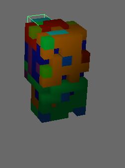
Yeah I do to some degree, but something is still not clear to me. Here is code that generates a box from within the game, for example:

    def gameBox(self,quadSide):
       widthIs=4
       lengthIs=4
       heightIs=4
       if(quadSide==1):
               #back:
               point1=Point3(0-widthIs,0,0)
               point2=Point3(0+widthIs,0,0)
               point3=Point3(0-widthIs,0,0+heightIs)
               point4=Point3(0+widthIs,0,0+heightIs)
       elif(quadSide==2):
               #front:
               point1=Point3(0-widthIs,0+lengthIs,0)
               point2=Point3(0+widthIs,0+lengthIs,0)
               point3=Point3(0-widthIs,0+lengthIs,0+heightIs)
               point4=Point3(0+widthIs,0+lengthIs,0+heightIs)
       elif(quadSide==3):
               #left:
               point1=Point3(0-widthIs,0,0)
               point2=Point3(0-widthIs,0+lengthIs,0)
               point3=Point3(0-widthIs,0,0+heightIs)
               point4=Point3(0-widthIs,0+lengthIs,0+heightIs)
       elif(quadSide==4):
               #right:
               point1=Point3(0+widthIs,0,0)
               point2=Point3(0+widthIs,0+lengthIs,0)
               point3=Point3(0+widthIs,0,0+heightIs)
               point4=Point3(0+widthIs,0+lengthIs,0+heightIs)
       elif(quadSide==5):
               #top:
               point1=Point3(0-widthIs,0,0+heightIs)
               point2=Point3(0+widthIs,0,0+heightIs)
               point3=Point3(0-widthIs,0+lengthIs,0+heightIs)
               point4=Point3(0+widthIs,0+lengthIs,0+heightIs)
       elif(quadSide==6):
               #bottom:
               point1=Point3(0-widthIs,0,0)
               point2=Point3(0+widthIs,0,0)
               point3=Point3(0-widthIs,0+lengthIs,0)
               point4=Point3(0+widthIs,0+lengthIs,0)
       x1=point1.x
       y1=point1.y
       minZ=point1.z
       #1.vertex:
       vertex.addData3f(x1,y1, minZ)
       normData=self.normalizer(Vec3(2*x1-1, 2*y1-1, 2*minZ-1))
       normal.addData3f(normData.x,normData.y,normData.z)
       color.addData4f(1, 1, 1, 1)
       texcoord.addData2f(0, 0)

       x2=point2.x
       y2=point2.y
       minZ=point2.z
       #2.vertex:
       vertex.addData3f(x2,y2, minZ)
       normData=self.normalizer(Vec3(2*x2-1, 2*y2-1, 2*minZ-1))
       normal.addData3f(normData.x,normData.y,normData.z)
       color.addData4f(1, 1, 1, 1)
       texcoord.addData2f(1, 0)

       x3=point3.x
       y3=point3.y
       minZ=point3.z
       #3.vertex:
       vertex.addData3f(x3,y3, minZ)
       normData=self.normalizer(Vec3(2*x3-1, 2*y3-1, 2*minZ-1))
       normal.addData3f(normData.x,normData.y,normData.z)
       color.addData4f(1, 1, 1, 1)
       texcoord.addData2f(0, 1)
        
       x4=point4.x
       y4=point4.y
       minZ=point4.z
       #4.vertex:
       vertex.addData3f(x4,y4, minZ)
       normData=self.normalizer(Vec3(2*x4-1, 2*y4-1, 2*minZ-1))
       normal.addData3f(normData.x,normData.y,normData.z)
       color.addData4f(1, 1, 1, 1)
       texcoord.addData2f(1, 1)
       
       #add to primitive:
       tris = GeomTriangles(Geom.UHDynamic)
       tris.addVertices(0, 1, 2)
       tris.addVertices(1, 2, 3)
       square = Geom(vdata)
       square.addPrimitive(tris)
       self.vertex_pool_data.append([point1,point2,point3,point4])
       return square

nodeTile = GeomNode("foundationTileGeomNode")
for i in range(6):
      gotGeom=self.gameBox(i+1)
      nodeTile.addGeom(gotGeom)
gameCube = render.attachNewNode(nodeTile)
gameCube.setTwoSided(True)
gameCube.setTransparency(TransparencyAttrib.MAlpha,1)

So from this code above, the points I’m using to define the cube that go into the “vertex.addData3f(x,y,z)” and that I use to define the normal data later on, those are global points in the world space, correct?

Now, here is that bit of code that will write the points as a vertex pool into the egg file:

vp = EggVertexPool('boxi2')
transformz=EggTransform()
#scale:
transformz.addScale3d(VBase3D(gameCube.getSx(render),gameCube.getSy(render),gameCube.getSz(render)))          
#rotation:
transformz.addRoty(gameCube.getR(render))
transformz.addRotx(gameCube.getP(render))
transformz.addRotz(gameCube.getH(render))
#translation:
transformz.addTranslate3d(VBase3D(gameCube.getX(render),gameCube.getY(render),gameCube.getZ(render)))
mat=transformz.getTransform3d()
...
#iterate through the point data used to define the box earlier and add it to the vertex pool:
faceData=self.vertex_pool_data[currentIndex]
p1=faceData[0]
p2=faceData[2]
p3=faceData[4]
p4=faceData[6]

v=EggVertex()
v.setPos(Point3D(p1.x,p1.y,p1.z))
v.transform(mat)
vp.addVertex(v)

Okay, so after filling the vertex pool with data, I use the points inside it to generate the normals that will go into the egg file (there’s some other stuff I do in between which is why I write it out at a separate portion of the code):

#now, get the point data added to the vertex pool and generate normals from it
#then write it out to the egg file:
vrtx=vp.getVertex(runningIndex)
pozzi=vrtx.getPos3()
#write out the normal data using this point:
self.f_wrt.write("<Normal> { ")
retz=self.normalizer(Vec3(2*pozzi.x-1, 2*pozzi.y-1, 2*pozzi.z-1))
self.f_wrt.write(str(retz.x)+" "+str(retz.y)+" "+str(retz.z)+" } ")

So…the points I’d be writing into the egg file, they are the global points of the box in the world, right? When generating procedural geometry, I just specify where each point and face should be, I never really thought about its local origin. In short, what should I do to a point used to define the box, before using it to generate normals and then writing those normals into the file, like in the example above?

No, the values that you pass to a GeomVertexWriter to generate a model are always the local coordinates, in object space. For instance if you pass (0., 0., 0.) then the resulting vertex will be at the origin of the model. If you set the position of the model node to e.g. (5., -3., 7.) then the local coordinates of that vertex are still (0., 0., 0.), but its world-space coordinates will be (5., -3., 7.).
So, ignoring any scale or rotation, the world-space coordinates of any vertex are the sum of its local coordinates and the positions of its own model node and all of its ancestor nodes.

You are right though that it’s these local coordinates that you need to define the normals.

So OK, you create each EggVertex, set local coordinates and then transform it with the net transform matrix so it ends up with world-space coordinates when adding it to the vertex pool, that’s fine.

And here’s where things go wrong. You retrieve a vertex from the vertex pool, but that vertex now has global coordinates (due to it being transformed with the net transform matrix previously), so you can’t use it to define its normal.

You could just store p1, p2, p3 and p4 of each square into a list called local_coords, for example, making sure to append them in the same order you add the EggVertex objects to the vertex pool. Later on, when you want to define the normals, instead of accessing the vertex pool, you get the point you need from the list.

The modified relevant bits of code could look like this:

v=EggVertex()
v.setPos(Point3D(p1.x,p1.y,p1.z))
v.transform(mat)
vp.addVertex(v)
self.local_coords.append(p1)

and this:

#now, get the point data added to the vertex pool and generate normals from it
#then write it out to the egg file:
pozzi=self.local_coords[runningIndex]

So the first vertex passed to the writer is treated as the origin of the model? Or is the model’s origin created some other way at some other point?

EDIT: Oh I get what you mean now! Silly me…:sweat: Any values I pass to the writer, say (3,4,5) will be relative to a point (0,0,0) that is not the origin of the world, but rather the origin of the model. So it would be (3,4,5) counting from (0,0,0) that is the model’s local origin point, is what you’re saying.
–end edit–

Regarding the proposed solution, I had actually attempted that this morning before posting a reply, since you had earlier mentioned transforms and differences in local and global space coordinates when it comes to calculating normal data as the culprit. However, while the generated normals were different, the lighting was still “hard”. I’ve now created 3 versions of the same asset which consists of 2 cubes; the first is the bam file where the lighting is smooth, the second is an egg file where world space coordinates are used to generate the normals and the third one is an egg file where local space coordinates are used to generate the normals. I’d expect the lighting in the third model to resemble that in the bam file but it’s still noticeably “harder”, even though it does differ from the lighting in the second model.
I’m terribly sorry to take your time like this, but I wonder what the reason could be, if there’s no other mistake on my part.

EDIT:
I am using pview to look at the models, not any program I’ve written.
–end edit–

normalTestSmooth.bam (6.0 KB)
worldSpaceNormals.egg (9.9 KB)
localSpaceNormals.egg (9.9 KB)

Ugh, I feel quite silly now too, because I should know that as long as the normals of all of the vertices at a certain point have the same direction, there really shouldn’t be any sharp edges! My sincere apologies; the choice of the point that the normals point away from doesn’t matter that much at all :frowning: .

What I notice now is that you have set a CullFaceAttrib on your models in the .bam file, likely due to a call to set_two_sided(True). Likewise, in the .egg files I see <BFace> { 1 } for each polygon. What probably happens is that Panda doubles the polys and inverts the duplicate normals when loading the .egg models, instead of applying a CullFaceAttrib.

So the real problem is that some of your triangles are created facing the wrong direction (due to incorrect winding order of the vertices), so when these are doubled the inverted normals will lead to hard edges.

The following modifications to your original code should lead to correctly facing triangles:

    def gameBox(self,quadSide):
       widthIs=4
       lengthIs=4
       heightIs=4
       if(quadSide==1):
               #back:
               point1=Point3(0-widthIs,0,0)
               point2=Point3(0+widthIs,0,0)
               point3=Point3(0+widthIs,0,0+heightIs)
               point4=Point3(0-widthIs,0,0+heightIs)
       elif(quadSide==2):
               #front:
               point1=Point3(0+widthIs,0+lengthIs,0)
               point2=Point3(0-widthIs,0+lengthIs,0)
               point3=Point3(0-widthIs,0+lengthIs,0+heightIs)
               point4=Point3(0+widthIs,0+lengthIs,0+heightIs)
       elif(quadSide==3):
               #left:
               point1=Point3(0-widthIs,0+lengthIs,0)
               point2=Point3(0-widthIs,0,0)
               point3=Point3(0-widthIs,0,0+heightIs)
               point4=Point3(0-widthIs,0+lengthIs,0+heightIs)
       elif(quadSide==4):
               #right:
               point1=Point3(0+widthIs,0,0)
               point2=Point3(0+widthIs,0+lengthIs,0)
               point3=Point3(0+widthIs,0+lengthIs,0+heightIs)
               point4=Point3(0+widthIs,0,0+heightIs)
       elif(quadSide==5):
               #top:
               point1=Point3(0-widthIs,0,0+heightIs)
               point2=Point3(0+widthIs,0,0+heightIs)
               point3=Point3(0+widthIs,0+lengthIs,0+heightIs)
               point4=Point3(0-widthIs,0+lengthIs,0+heightIs)
       elif(quadSide==6):
               #bottom:
               point1=Point3(0-widthIs,0+lengthIs,0)
               point2=Point3(0+widthIs,0+lengthIs,0)
               point3=Point3(0+widthIs,0,0)
               point4=Point3(0-widthIs,0,0)

and:

       #add to primitive:
       tris = GeomTriangles(Geom.UHDynamic)
       tris.addVertices(0, 1, 2)
       tris.addVertices(0, 2, 3)

Don’t forget to remove the <BFace> { 1 } entries from the .egg file.

Again, sorry for the confusion!

No worries, your help is always indispensable. Okay, removing the backface attribute does indeed result in smoother lighting,albeit I still have to call “.setTwoSided(True)” after loading up the egg file. There is one thing you’re saying that I don’t quite follow. Here is how I usually define the faces I use to create the models in game:

The total face:
p2----p3
|     |
p0----p1

The triangles:
p2
|
p0---p1

And
p2----p3
      |
      p1

So to the geomtriangles, I would add the points thus:

       tris = GeomTriangles(Geom.UHDynamic)
       tris.addVertices(0, 1, 2)
       tris.addVertices(1, 2, 3)

I do this for all faces in whatever model is being generated in the game. So defining a face like this would mean some faces would be drawn “facing the front” while others “facing the back”? This is why I was using “setTwoSided(True)” on models, as well as adding the backface attribute to the egg files I generated in-game.
So what’s the right way to define a face so that it always “faces the front” thus removing the need for the “setTwoSided” call?

That is determined by the winding order; I think the vertices in the addVertices call should be ordered counter-clockwise.

Indeed; to elaborate on rdb’s answer, you have to imagine yourself looking straight at the side of the triangle that you want to be drawn/visible/rendered/whatever. Then you start at any of the three vertices and add their indices to add_vertices as you encounter them when looking at them in counter-clockwise order.

So when you apply this to the point configurations you pictured, the indices of the first triangle could be ordered as (0, 1, 2), (1, 2, 0) or (2, 0, 1). Likewise, the indices of the second triangle can be ordered as (1, 3, 2), (3, 2, 1) or (2, 1, 3)… but not (1, 2, 3) as in your code.

Okay, thank you Epihaius and rdb for your help. So when using procedural geometry:

  • Define your faces with correct winding order to avoid using “.setTwoSided(True)”.
  • If you don’t care much for winding order and want smooth lighting, when saving your egg files, do not add the backface attribute, but upon loading your model into the game, call “.setTwoSided(True)” on it to make sure some triangles aren’t invisible when viewed “from the back”.
  • As long as the normals of all of the vertices at a certain point have the same direction, there really shouldn’t be any sharp edges. (To quote Mr. Epihaius).

Thank you once more as always.