Issues with normals of procedurally generated GeomTriangles

Hello,

I’m struggling a bit with the normals of generated geometries. The code I use is the following

 43     #all the vertices have normal (0,0,1)
 44     #triangles : = an array of vertex indices
 45     for t in triangles:
 46         prim = GeomTriangles(Geom.UHStatic)
 47         prim.addVertex(t[0])
 48         prim.addVertex(t[1])
 49         prim.addVertex(t[2])
 50         prim.closePrimitive()
 51
 52         geom.addPrimitive(prim)
 53
 54         if geom.getNumPrimitives() > 2000:
 55             gnode.addGeom(geom)
 56             i+=1
 57             geom = Geom(vdata)
 58
 59     render.attachNewNode(gnode)

which produces the following result:

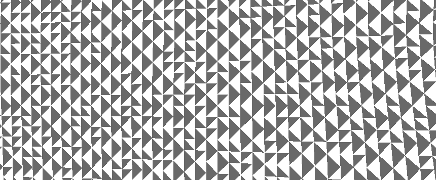
as you can see, some of the normals are flipped…

is there any way to fix this? :slight_smile:

You can set the direction of the normals explicitly. You need to use a format that contains columns to store the vector. For example, this one: v3n3

https://docs.panda3d.org/1.10/python/programming/internal-structures/procedural-generation/predefined-vertex-formats

Or create your own format.

https://docs.panda3d.org/1.10/python/programming/internal-structures/procedural-generation/custom-vertex-format

array = GeomVertexArrayFormat()
array.add_сolumn("vertex", 3, Geom.NTFloat32, Geom.C_point)
array.add_сolumn("normal", 3, Geom.NT_float32, Geom.C_normal)

Next, you can specify the desired vector.

normal = GeomVertexWriter(vdata, 'normal')
normal.add_data3(0, 0, 1)

It looks to me like the problem is less with the normals, as such, than with the winding order of your triangles.

(If I’m correct in interpreting one of those colours as being the background colour.)

In short, by default the engine culls away polygons that are considered to be “facing away from the camera”, and it determines this, I believe, by the order of their vertices–specifically, by whether going through them one after another produces a loop that is clockwise or anticlockwise from the current view. (This is commonly called “backface culling”, I believe.)

I’m guessing, then, that you vertices are laid out such that every second set loops clockwise, and every other loops anticlockwise–resulting in half of your triangles being culled away.

This might be addressed either by one of three approaches, I think:

  1. Reworking the order of your vertices such that they’re always either clockwise or anticlockwise (as appropriate)
  2. Reworking the code that adds vertices to take into account the (presumed, admittedly) swapping of winding order
  3. Or disabling backface culling.

(That last may have consequences, however, depending on your purposes: backface culling is a feature intended to improve performance.)

Thank you both for your answers.

I agree! The issue is with the winding order. The problem is that I’m not sure how to make it right. As far as you know, is there any way to programmatically determine the correct winding order?

I think, I’ve made some progress. According with this post there is a way to determine the winding order.

Only, it has to be done with respect to a viewpoint(obviously). By setting V = (0,0,1), I have obtained this result:

as you can see, the issue seems to be that (0,0,1) is not a good point of view for each vertex. Do you have any idea on how to set it to match the mesh’s shape?

Well, the simplest way of course is perhaps to just generate them in the correct order in the first place. :stuck_out_tongue:

But if that’s not feasible, or is otherwise not desirable, you can perhaps do what I think that the engine does: take the cross product of two of the edges.

Now, I’m going by memory, and haven’t tested the following, so I do very much stand to be corrected. That said:

You see, the cross product of two triangle edges should be a vector pointing at ninety degrees to both–and thus at ninety degrees from the plane of the triangle. And, importantly, it should have the same direction for all clockwise pairs of vectors, and the same, opposite direction for all anticlockwise pairs of vectors.

Thus if you get the cross product of a triangle that you know to be correct, then you can test all subsequent triangles and reverse the order of the ones that have opposing cross products. Or, if you know a direction that you can test against, you can simply make a vector that points in that direction.

Something like this:

# Presume that you have already come up with
# vector that points in the desired direction,
# called "referenceVector"

for t in triangles:
    prim = GeomTriangles(Geom.UHStatic)

    vector1 = t[0] - t[1]
    vector2 = t[1] - t[2]
    crossProdVector= vector1.cross(vector2)

    # The dot product of two vectors is
    # greater than zero if they point in
    # more-or-less the same direction,
    # and less than zero if they point in
    # more-or-less the opposite direction.
    if crossProdVector.dot(referenceVector) > 0:
        # Do what you normally do here
        prim.addVertex(t[0])
        prim.addVertex(t[1])
        prim.addVertex(t[2])
    else:
        # Reverse the direction here
        prim.addVertex(t[0])
        prim.addVertex(t[2])
        prim.addVertex(t[1])

    prim.closePrimitive()

    # Continue as per normal...

Yes, that’s what I’m trying to do. The problem is to come up with a satisfying reference vector. What I’m doing now, which produces the result above, is setting such vector to (0,0,1).

Ah, I see–my apologies!

Hmm… It’s strange that it doesn’t work… And more so that it seems to work in regions, rather than either arbitrarily or for every second triangle…

Is your surface flat? If not, what shape does it have? For example, are those dark regions perhaps regions that have a vertical position above zero, and the light regions those that have a vertical position below zero (or vice versa)?

And–if feasible, and if your surface isn’t flat–what happens if you try a flat surface?

No, my surface isn’t flat. I suppose that is the problem. My guess it that only the sufficiently flat parts are done correctly(since the reference vector is (0,0,1)). I’ll try with the flat surface and post the result. But I’m almost sure it will be rendered correctly :slight_smile:

I am interested to see the result!

To be clear, however, this should, I think, work even for a non-flat surface. Given that it’s not working for a non-flat surface, if it does then work for a flat surface, the next question will be that of why there is this discrepancy…

As I said, it may help for us to know the shape in question (including whether it’s vertical position that determines it). And it may prove useful to see the relevant code.

But first, let’s see what happens with that flat surface!

Here is the result for a flat surface:

Selection_015

generated with the following code:

169     points = []
170     triangles = []
171     for i in range(0,10):
172         for j in range(0,10):
173             points.append([10 * i,10*j,0])
174
175
176     for i in range(0,9):
177         for j in range(0,9):
178             tri1 = [i * 10 + j, i*10 + j + 1 , (i+1)*10 + j + 1]
179             tri2 = [i * 10 + j, (i+1) * 10 + j, (i+1) * 10 + j + 1]
180             triangles.append(tri1)
181             triangles.append(tri2)

by the way, the source code can be found here. As you can notice, it is a fork from another project which uses blender for visualization(see procedural_city_generation/visualization/blenderize.py). I’ m simply using the data generated from the steps which precede visualization to instance an .egg file. The code which concern us can be found in fromPyDataEgg() in the Connector.py file :slight_smile:
(Yes, since I was interested in producing an egg file, I switched to the egg interface).

The function called in fromPyDataEgg() which determines and updates the winding order is called updateWindingOrder() and can be found in the same file.

BTW, for completeness, If you would like to run the code, install the deps:

pip install -r requirements.txt

and call

python MAIN.py

after visualization, you should be able to find the generated egg file as test.egg

NOTE: for the time being, the visualization is very slow!

Ah, well, it does look to me that the generation step is producing alternating winding-orders. Consider the following set of points:

       j    j+1
i      *     *
i+1    *     *

The first triangle-defining line of the generating code should, I think, produce the following:

(i, j)--->(i, j+1)--->(i+1, j+1)
1---->2
  \   |
    \ |
      V
      3

Note that, as viewed here, the triangle winds clockwise.

On the other hand, the next line of that code should, I think, produce the following:

(i, j)--->(i+1, j)--->(i+1, j+1)
1<---3
|   /^
| /
V
2

Note that, as viewed here, this triangle winds anticlockwise.

So, if you can change the code, then it might be worth just changing the winding order specified there such that it’s consistent.

As to the flat surface, that is interesting! My best guess right now is that there’s some error in the code that calculates the dot-products (perhaps it’s using the positions of the vertices, rather than the differences between positions…?)–or that there’s an error in the concept somewhere (as I said of my version above, I was going by memory and hadn’t tested what I wrote, so it’s possible that I’m wrong in some way).